# Cabinet details
The system has added a cabinet display for energy storage units/voltage regulation units in industrial and commercial storage type power stations. You can view the basic information of your cabinet on the device.
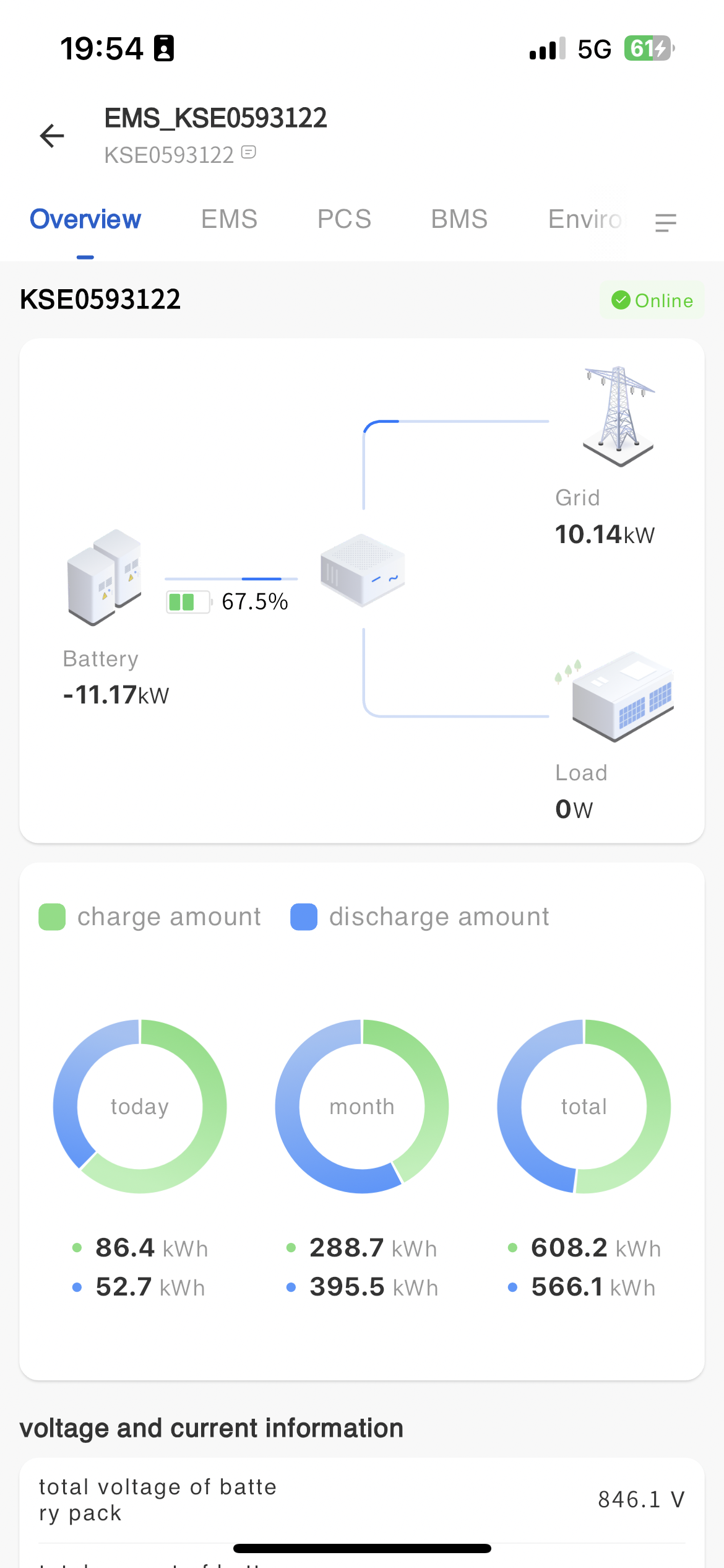
# Overview of Energy Storage Units
You can click on the cabinet data you want to view on the device page to enter the details page. On the matchmaking page, the system displays the working energy flow chart, battery working basic information, and load working basic information of the current cabinet.
# PCS monitoring
Real time information
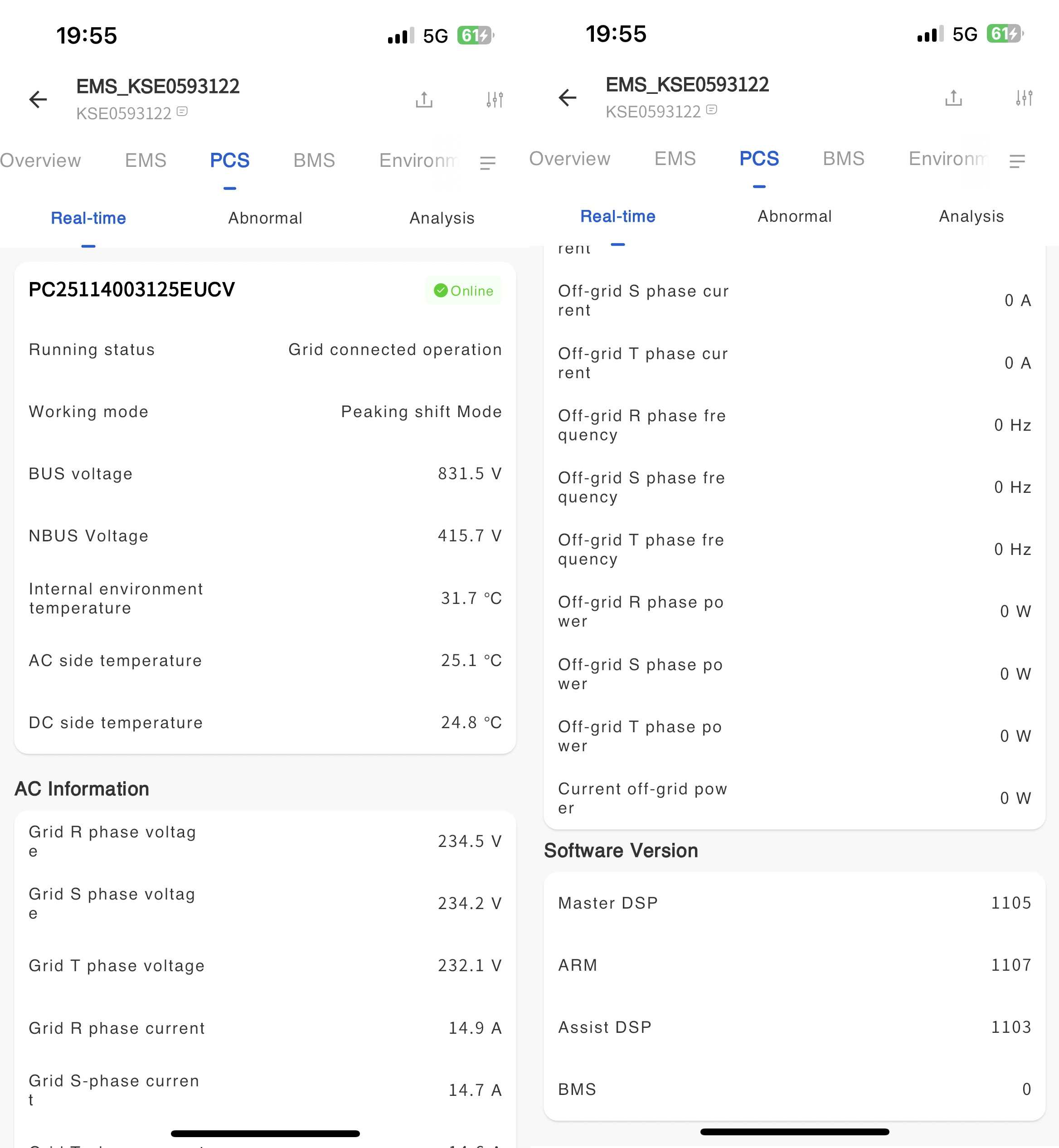
The real-time information page displays detailed working data of the device, including device status, power generation data, grid data, temperature, control, and version number (updated every five minutes).
-Fault information
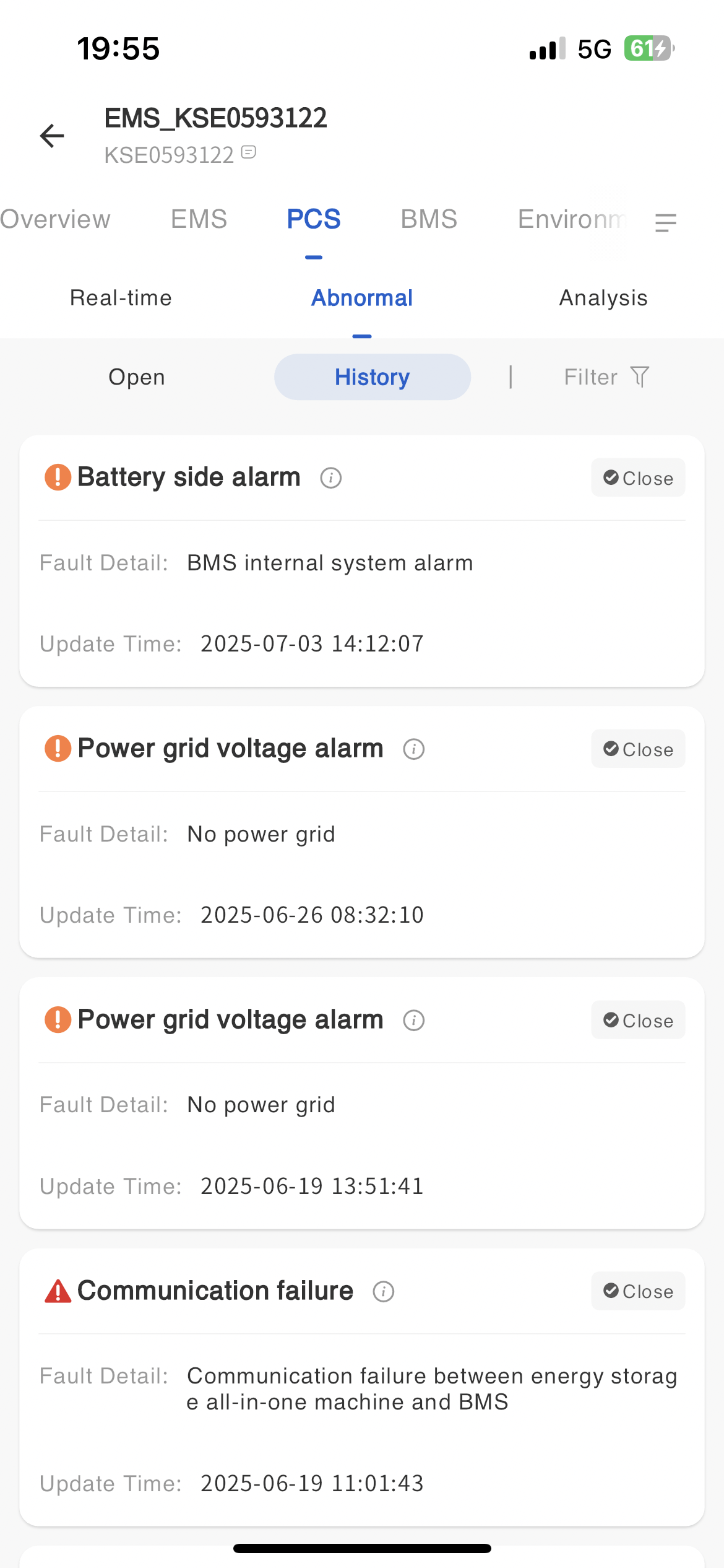
In the fault information page, display all fault data of the device. Move the button next to the mouse fault type to view the troubleshooting plan for the fault alarm.
-Statistical analysis
The statistics page displays the current real-time power, historical power, AC analysis, DC current comparison, DC voltage comparison, DC current and voltage comparison, and historical power generation of the device in the form of a line chart.
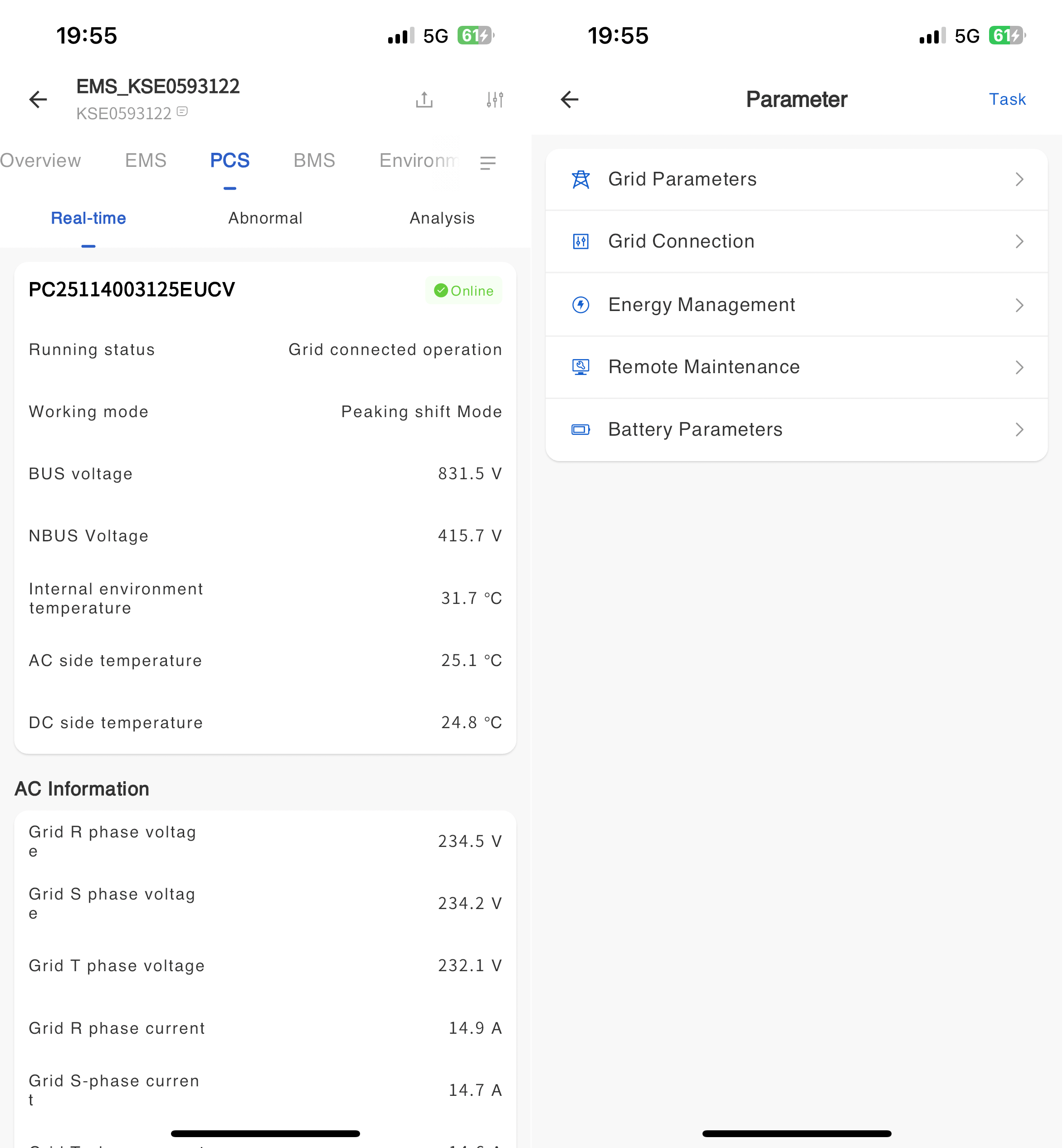
# Equipment parameter configuration
Remote reading, setting, and self checking of device operating parameters (only supports some models of devices).
Global configuration steps
① Click on the power station - Power Station Management - Power Station List to enter the power station details.
② Click on the device information on the left to enter the associated device list page.
③ Click the [Configuration] button on the right.
④ In the pop-up parameter configuration page, select the parameter type that needs to be set.
⑤ On the corresponding parameter type page, enter the parameter value that needs to be modified and click the [Settings] button.
# Grid parameters

| Parameter | Parameter Description | Parameter range |
|---|---|---|
| Country | Setting different countries, regulations will display corresponding content | |
| laws and regulations | After setting regulations, relevant information such as grid connection parameters, protection&time, etc. will be automatically modified to the corresponding regulatory settings. | |
| Auto Test | Used to check and verify the operational status, performance, and safety of inverters. (When choosing Italy as the country, the Auto Test function can be used) |
# Grid connection parameters
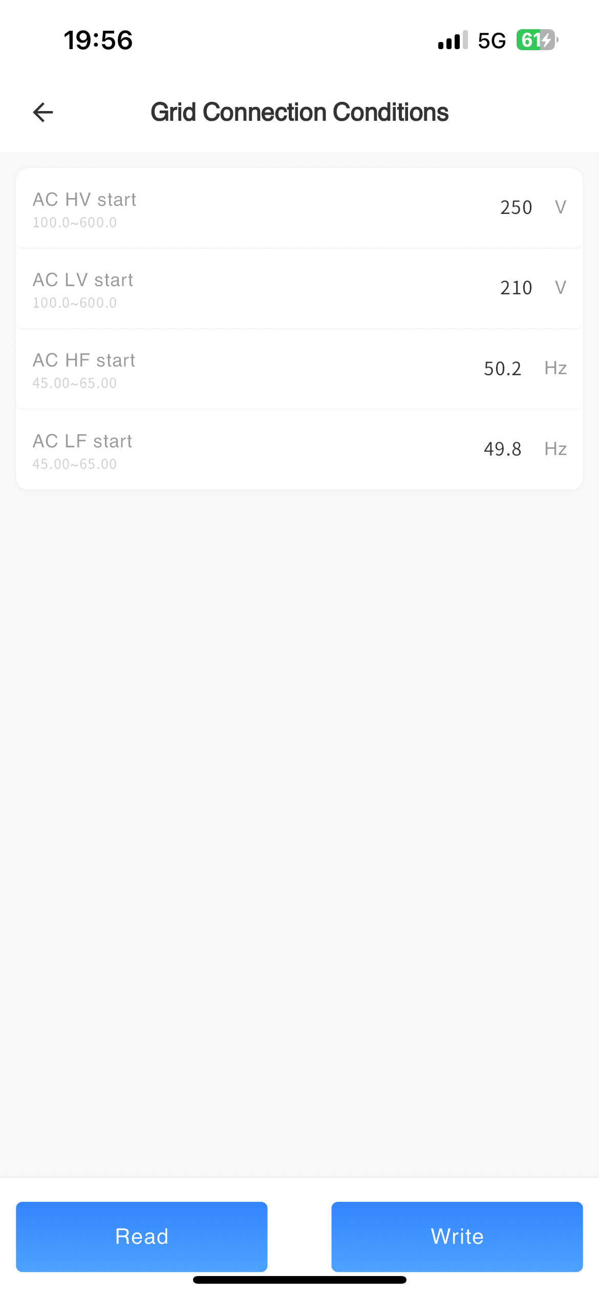
Grid connection conditions
| Parameter | Parameter Description | Parameter range |
|---|---|---|
| AC startup high voltage(V) | The highest mains voltage that a machine can connect to the grid. If the machine detects that the mains voltage exceeds this voltage before grid connection, it will not be able to connect to the grid (the regulations will be automatically modified to the corresponding regulatory settings, and it is not recommended for users to modify) | 100V-600V,Minimum Unit 0.1V |
| AC startup low voltage | The minimum mains voltage at which a machine can connect to the grid. If the machine detects that the mains voltage is lower than this voltage before grid connection, it will not be able to connect to the grid (the regulations will be automatically modified to the corresponding regulatory settings, and it is not recommended for users to modify) | 100V-600V,Minimum Unit 0.1V |
| AC startup high-frequency(Hz) | The highest mains frequency at which a machine can connect to the grid. If the machine detects that the mains frequency exceeds this frequency before grid connection, it will not be able to connect to the grid (the regulations will be automatically modified to the corresponding regulatory settings, and it is not recommended for users to modify) | 45Hz-65Hz,Minimum Unit 0.01Hz |
| AC startup low frequency(Hz) | The minimum mains frequency at which a machine can connect to the grid. If the machine detects that the mains voltage is lower than this frequency before grid connection, it will not be able to connect to the grid (the regulations will be automatically modified to the corresponding regulatory settings, and it is not recommended for users to modify) | 45Hz-65Hz,Minimum Unit 0.01Hz |
| Waiting time for grid connection | The waiting time before the first grid connection after the machine is turned on (setting regulations will automatically modify to the corresponding regulatory settings, and it is not recommended for users to modify) | 1s-65535s,Minimum 1s |
| Grid reconnection time | The waiting time before the machine is reconnected to the grid due to standby or disconnection from the mains power, etc. (The setting of regulations will automatically modify to the corresponding regulatory setting value, and it is not recommended for users to modify it) | 1s-65535s,Minimum 1s |
| First grid connection rising slope(X%Pn/min) | The rate at which the machine tracks to the maximum power point of MPPT after being connected to the grid for the first time after startup (the setting of regulations will automatically modify to the corresponding regulatory setting value, and it is not recommended for users to modify it) | 1-65535,Minimum 1X%Pn/min |
| Reconnect and increase the online slope(X%Pn/min) | The rate at which the machine tracks to the maximum power point of MPPT after reconnecting to the grid (setting regulations will automatically modify to the corresponding regulatory setting value, it is not recommended for users to modify) | 1-65535,Minimum 1X%Pn/min |
| Low voltage crossing enable | Enable low voltage ride through function after activation | Enable/Disable |
| High voltage crossing enable | Enable high voltage ride through function after activation | Enable/Disable |
| Zero current ride through enable | Enable zero current ride through function after activation | Enable/Disable |
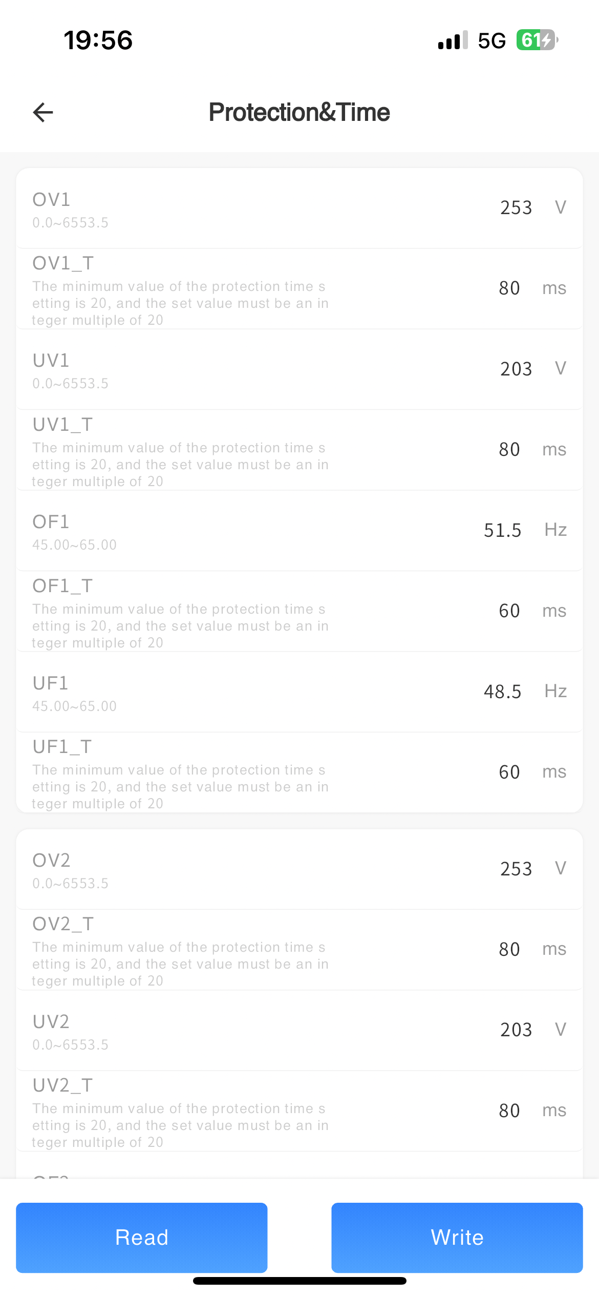
Protection&Time
| Parameter | Parameter Description | Parameter range |
|---|---|---|
| UV1 (V) | When the machine detects that the mains voltage is too low, it will protect and report a level 1 undervoltage fault (the setting regulations will automatically modify to the corresponding regulatory setting values, and it is not recommended for users to modify) | Minimum 0.1V |
| OV1 (V) | When the machine detects that the mains voltage is too high, it will protect and report a level 1 overvoltage fault (the setting regulations will automatically modify to the corresponding regulatory setting values, and it is not recommended for users to modify) | Minimum 0.1V |
| UF1 (Hz) | When the machine detects that the mains frequency is low to this frequency, it will protect and report a level 1 underfrequency fault (setting regulations will automatically modify to the corresponding regulatory setting value, it is not recommended for users to modify) | Minimum 0.01Hz |
| OF1 (Hz) | When the machine detects that the mains frequency is too high at this frequency, it will protect and report a level 1 overclocking fault (setting regulations will automatically modify to the corresponding regulatory setting value, it is not recommended for users to modify) | Minimum 0.01Hz |
| UV1_T (ms) | The time taken from level 1 undervoltage of the mains power to machine protection (setting regulations will automatically modify to the corresponding regulatory setting value, it is not recommended for users to modify) | Minimum 20ms |
| OV1_T (ms) | The time taken from level 1 overvoltage of the mains power to machine protection (the setting of regulations will automatically modify to the corresponding regulatory setting value, and it is not recommended for users to modify) | Minimum 20ms |
| UF1_T(ms) | The time taken from underfrequency at level 1 of the municipal power supply to machine protection (setting regulations will automatically modify to the corresponding regulatory settings, and it is not recommended for users to modify) | Minimum 20ms |
| OF1_T (ms) | The time taken from level 1 overclocking of the mains power to machine protection (setting regulations will automatically modify to the corresponding regulatory setting value, and it is not recommended for users to modify) | Minimum 20ms |
| UV2 (V) | When the machine detects that the mains voltage is too low, it will protect and report a level 2 undervoltage fault (the setting regulations will automatically modify to the corresponding regulatory setting values, and it is not recommended for users to modify) | Minimum 0.1V |
| OV2 (V) | When the machine detects that the mains voltage is high enough, it will protect and report a level 2 overvoltage fault (the setting regulations will automatically modify to the corresponding regulatory setting values, and it is not recommended for users to modify) | Minimum 0.1V |
| UF2 (Hz) | When the machine detects that the mains frequency is low to this frequency, it will protect and report a level 2 underfrequency fault (setting regulations will automatically modify to the corresponding regulatory setting value, it is not recommended for users to modify) | Minimum 0.01Hz |
| OF2 (Hz) | When the machine detects that the mains frequency is too high at this frequency, it will protect and report a level 2 overclocking fault (setting regulations will automatically modify to the corresponding regulatory setting value, it is not recommended for users to modify) | Minimum 0.01Hz |
| UV2_T (ms) | The time taken from under voltage at level 2 of the mains power supply to machine protection (the setting of regulations will automatically modify to the corresponding regulatory setting value, and it is not recommended for users to modify it) | Minimum 20ms |
| OV2_T (ms) | The time taken from overvoltage level 2 of the mains power to machine protection (setting regulations will automatically modify to the corresponding regulatory setting value, it is not recommended for users to modify) | Minimum 20ms |
| UF2_T(ms) | The time taken from underfrequency at level 2 of the mains power to machine protection (setting regulations will automatically modify to the corresponding regulatory settings, and it is not recommended for users to modify) | Minimum 20ms |
| OF2_T (ms) | The time taken from overclocking at level 2 of the mains power to machine protection (setting regulations will automatically modify to the corresponding regulatory settings, and it is not recommended for users to modify) | Minimum 20ms |
| UV3 (V) | When the machine detects that the mains voltage is too low, it will protect and report a level 3 undervoltage fault (the setting regulations will automatically modify to the corresponding regulatory setting values, and it is not recommended for users to modify) | Minimum 0.1V |
| OV3 (V) | When the machine detects that the mains voltage is high enough, it will protect and report a level 3 overvoltage fault (the setting regulations will automatically modify to the corresponding regulatory setting values, and it is not recommended for users to modify) | Minimum 0.1V |
| UF3 (Hz) | When the machine detects that the mains frequency is low to this frequency, it will protect and report a level 3 underfrequency fault (setting regulations will automatically modify to the corresponding regulatory setting value, it is not recommended for users to modify) | Minimum 0.01Hz |
| OF3 (Hz) | The machine detects that the mains frequency is too high and will protect it, reporting a level 3 overclocking fault (setting regulations will automatically modify to the corresponding regulatory setting value, it is not recommended for users to modify) | Minimum 0.01Hz |
| UV3_T (ms) | The time taken from level 3 undervoltage of the mains power to machine protection (setting regulations will automatically modify to the corresponding regulatory setting value, it is not recommended for users to modify) | Minimum 20ms |
| OV3_T (ms) | The time taken from level 3 overvoltage of the mains power to machine protection (setting regulations will automatically modify to the corresponding regulatory setting value, and it is not recommended for users to modify) | Minimum 20ms |
| UF3_T(ms) | The time taken from underfrequency at level 3 of the mains power to machine protection (setting regulations will automatically modify to the corresponding regulatory settings, and it is not recommended for users to modify) | Minimum 20ms |
| OF3_T (ms) | The time taken from overclocking at level 3 of the mains power to machine protection (setting regulations will automatically modify to the corresponding regulatory settings, and it is not recommended for users to modify) | Minimum 20ms |
| 10 min OV Protection (V) | When the grid voltage exceeds 1.1 times, the inverter should operate for at least 10 minutes (conflicting with the overvoltage protection function, which requires setting the overvoltage protection time to be greater than 10 minutes) | Minimum0.1V |
Power

| Parameter | Parameter Description | Parameter range |
|---|---|---|
| Active power % (%) | After setting the value, the maximum power of the machine becomes the maximum power multiplied by the set percentage | Minimum0.1% |
| P(U) Curve Enable | After setting, the machine works according to the P (U) curve | On/Off |
| V1(V) | After setting the value, the equipment adjusts to the voltage value after the power grid is overvoltage | Minimum 0.1V |
| V2(V) | After setting the value, the equipment adjusts to the voltage value after the power grid is overvoltage | Minimum 0.1V |
| V3(V) | After setting the value, the equipment adjusts to the voltage value after the power grid is overvoltage | Minimum 0.1V |
| V4(V) | After setting the value, the equipment adjusts to the voltage value after the power grid is overvoltage | Minimum 0.1V |
| V1_P(%) | After setting the value, the equipment adjusts the power to the value after overvoltage in the power grid | Minimum 0.1% |
| V2_P(%) | After setting the value, the equipment adjusts the power to the value after overvoltage in the power grid | Minimum 0.1% |
| V3_P(%) | After setting the value, the equipment adjusts the power to the value after overvoltage in the power grid | Minimum 0.1% |
| V4_P(%) | After setting the value, the equipment adjusts the power to the value after overvoltage in the power grid | Minimum 0.1% |
| T (s) | After setting the value, the equipment will automatically adjust after experiencing the overvoltage of the power grid for a certain period of time | Minimum 1s |
| Power response switch | After enabling, the reactive power response speed can be set, otherwise it will respond at the fastest speed | On/Off |
| T (s) | Set reactive power response time constant | |
| Reactive regulation method | The specific standards supported by the device under the national/regional power grid should be selected based on the current grid standards connected to the device. | Disable Power factor setting enabled Reactive power percentage setting enabled Q (U) curve setting enabled Q (P) curve setting enabled |
| Reactive power % (%) | Reactive power percentage can be set | Minimum 0.1% |
| power factor | Power factor value can be set | 0.001 |
| Q(P) Curve Type | Q (P) curve can be set |
Curve A Curve B Curve C |
| PA (%) | The specific standards supported by the device under the national/regional power grid should be selected based on the current grid standards connected to the device. | |
| PA_P | The specific standards supported by the device under the national/regional power grid should be selected based on the current grid standards connected to the device. | |
| PB (%) | The specific standards supported by the device under the national/regional power grid should be selected based on the current grid standards connected to the device. | |
| PB_P | The specific standards supported by the device under the national/regional power grid should be selected based on the current grid standards connected to the device. | |
| PC (%) | The specific standards supported by the device under the national/regional power grid should be selected based on the current grid standards connected to the device. | |
| PC_P | The specific standards supported by the device under the national/regional power grid should be selected based on the current grid standards connected to the device. | PD (%) | The specific standards supported by the device under the national/regional power grid should be selected based on the current grid standards connected to the device. |
| PD_P | The specific standards supported by the device under the national/regional power grid should be selected based on the current grid standards connected to the device. | |
| T (s) | The specific standards supported by the device under the national/regional power grid should be selected based on the current grid standards connected to the device. | |
| Enable Q(P) Voltage (%) | The specific standards supported by the device under the national/regional power grid should be selected based on the current grid standards connected to the device. | |
| Disable Q(P) Voltage (%) | The specific standards supported by the device under the national/regional power grid should be selected based on the current grid standards connected to the device. | |
| Disable Q(P) Power (%) | The specific standards supported by the device under the national/regional power grid should be selected based on the current grid standards connected to the device. | |
| Q(U) Curve Type | Q (U) curve can be set | Curve A Curve B Curve C |
| U1 (%) | The specific standards supported by the device under the national/regional power grid should be selected based on the current grid standards connected to the device. | |
| U1_P (%) | The specific standards supported by the device under the national/regional power grid should be selected based on the current grid standards connected to the device. | |
| U2 (%) | The specific standards supported by the device under the national/regional power grid should be selected based on the current grid standards connected to the device. | |
| U2_P (%) | The specific standards supported by the device under the national/regional power grid should be selected based on the current grid standards connected to the device. | |
| U3 (%) | The specific standards supported by the device under the national/regional power grid should be selected based on the current grid standards connected to the device. | |
| U3_P (%) | The specific standards supported by the device under the national/regional power grid should be selected based on the current grid standards connected to the device. | |
| U4 (%) | The specific standards supported by the device under the national/regional power grid should be selected based on the current grid standards connected to the device. | |
| U4_P (%) | The specific standards supported by the device under the national/regional power grid should be selected based on the current grid standards connected to the device. | |
| Enable Q(U) Power (%) | The specific standards supported by the device under the national/regional power grid should be selected based on the current grid standards connected to the device. | |
| Disable Q(U) Power (%) | The specific standards supported by the device under the national/regional power grid should be selected based on the current grid standards connected to the device. | |
| Reactive power response time constant (s) | The specific standards supported by the device under the national/regional power grid should be selected based on the current grid standards connected to the device. | |
| Active power setting value(kW) | ||
| Reactive power setting value(kVar) | ||
| LVRT zero power mode | ||
| HVRT zero power mode | ||
| Overclocking derating switch | ||
| Overclocking derating curve type | ||
| Derating frequency point F1 (start point)(Hz) | ||
| Overdrive derating frequency point F2 (end point) (Hz) | ||
| Overdrive derating frequency point F3 (Reserved) (Hz) | ||
| Power setting at F1 frequency point (%) | ||
| Power setting at F2 frequency point (%) | ||
| Power setting at F3 frequency point (%) | ||
| Frequency point for over-frequency derating power recovery (Hz) | ||
| Power slope of over-frequency derating (%/min) | ||
| Over-frequency Derating Recovery Time(s) | ||
| Over-frequency Derating Recovery Slope(%/min) |
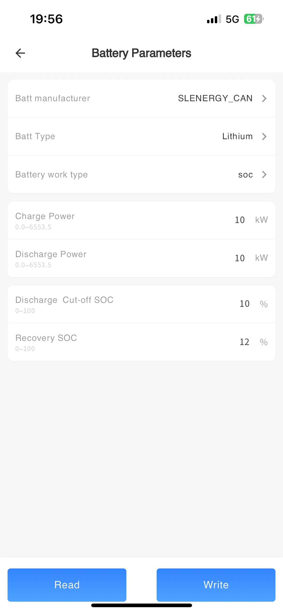
# Battery
| Parameter Name | Parameter Description | Parameter Range |
|---|---|---|
| Batt manufacturer | Set the manufacturer of the battery. | Zhongxing Paineng_CAN Zhongxing Paineng_RS485 Tianbang Da_CAN Tianbang Da_RS485 Xinwangda_CAN Xinwangda_RS485 BYD_CAN BYD_RS485 Youneng_CAN Youneng_RS485 Jiabaida_CAN Jiabaida_RS485 AOBOET_CAN AOBOET_RS485 SLENERGY_CAN SLENERGY_RS485 DESAY_CAN DESAY_RS485 GENIXGEREEN_CAN GENIXGEREEN_RS485 DYNESS_CAN DYNESS_RS485 |
| Batt Type | Select the type of battery | No Batt/Lead-acid/Lithum |
| Battery operation type | Select battery operating mode | Voltage/SOC/No Batt |
| Discharge Cut-off Volt in Hybrid mode (V) | In the presence of PV, after setting the value, the battery voltage will stop discharging when it is lower than the set value | Minimum setting 0, minimum unit 0.1V |
| Discharge Cut-off SOC in Hybrid mode (%) | In the presence of PV, after setting the value, the battery will discharge until the SOC is lower than the set value, and then stop discharging | Minimum setting 0, minimum unit 1% |
| Recovery Volt in Hybrid mode (V) | In the presence of PV, after setting the value, discharging is allowed when the battery voltage is higher than the set value | Minimum setting 0, minimum unit 0.1V< |
| Recovery SOC in Hybrid mode (%) | In the presence of PV, after setting the value, the battery is allowed to discharge after charging to SOC higher than the set value | Minimum setting 0, minimum unit 1% |
| Max Discharge (A) | Set the maximum discharge current of the battery | Minimum setting 0, minimum unit 1A |
| Max Charge (A) | Set the maximum charging current of the battery | Minimum setting 0, minimum unit 1A |
| Charge Power (kW) | Set the maximum charging power of the battery | Minimum setting 0, minimum unit 0.1kW |
| Discharge Power (kW) | Set the maximum discharge power of the battery | Minimum setting 0, minimum unit 0.1kW |
| Power-on activated Batt enable | Enable and power on to activate the battery | Open/Close |
| Active Batt Enable | Activate the battery continuously after enabling | Open/Close |
| Charge Enable | After enabling, the battery can be charged (1. Direct charging with PV; 2. Preconditions for grid charging) | Open/Close |
| Grid-tie Enable | After enabling, the machine and battery are connected to the grid (a prerequisite for battery connection) | Open/Close |
| Batt Grid-tie Enable | After enabling, the main grid switch is also enabled, and the machine battery can be connected to the grid | Open/Close |
| AC Charging Max current (A) | Set the maximum charging current of the battery to the mains power supply | Minimum setting 0, minimum unit 1A |
| AC charging target SOC (%) | Set the SOC for charging the battery using mains power | Minimum setting 0, minimum unit 1% |
| AC charging target Volt (V) | Set the voltage for charging the battery using mains power | Minimum setting 0, minimum unit 0.1V |
| Battery capacity (Ah) | Set according to the actual installed battery capacity | Minimum setting 0, minimum unit 1Ah |
| Lithium battery loss report fault switch | After setting, if the battery BMS cannot communicate with the inverter, the inverter will stop working and report a fault | Open/Close |
| Discharge Cut-off Volt (V) | When the battery voltage is below this set threshold, the battery cannot generate electricity | Minimum setting 0, minimum unit 0.1V |
| Recovery Volt (V) | When the battery voltage exceeds the threshold set, the battery can be discharged | Minimum setting 0, minimum unit 0.1V |
| Discharge Cut-off SOC (%) | After setting the value, the battery will stop discharging when the SOC is lower than the set value | Minimum setting 0, minimum unit 1% |
| Recovery SOC (%) | After setting the value, the battery will resume discharging when the SOC is higher than the set value | Minimum setting 0, minimum unit 1% |
| Chai Fa Charging Switch | After setting up, use a generator to charge the connected battery pack | Open/Close |
| Diesel charging current (A) | Can set the generator to charge the battery current | Minimum setting 0, minimum unit 1A |
| Chai Fa Signal | Set the discharge power of the energy storage device. | Realy normally open/Relay closure |
| Diesel engine forced opening | When the generator is connected, it is forced to start the generator without meeting other conditions | Open/Close |
| AC Charge Enable | After setting up, use the power grid to charge the connected battery pack | Open/Close |
| Grid Charge Activation Volt (V) | When the battery voltage falls below this set threshold, the power grid begins to forcefully charge the battery | Minimum setting 0, minimum unit 0.1V |
| Grid Charge Activation SOC (%) | When the SOC of the battery falls below this set threshold, the power grid begins to forcibly charge the battery | Minimum setting 0, minimum unit 1% |
| Grid charging current (A) | Can set the charging current of the battery to the power grid | Minimum setting 0, minimum unit 1A |
| Power grid signal | Set the discharge power of the energy storage device. | Minimum 0, minimum unit 0.1kW |
| Float Volt (V) | Set the float charging voltage for lead-acid batteries | Minimum setting 0, minimum unit 0.1V |
| Absorption Volt (V) | Set the constant voltage charging voltage for lead-acid batteries | Minimum setting 0, minimum unit 0.1V |
| Balanced charging voltage (V) | Set the balanced charging voltage for lead-acid batteries | Minimum setting 0, minimum unit 0.1V |
| Balanced charging cycle (days) | Set the balanced charging cycle for lead-acid batteries | Minimum setting 0, minimum unit 1Day |
| Balanced charging duration (hours) | Set the balanced charging duration for lead-acid batteries | Minimum setting 0, minimum unit 1 hour |
| Under voltage alarm voltage (V) | Alarm lead-acid and lithium batteries when they reach the set voltage value | Minimum setting 0, minimum unit 0.1V |
| Under voltage alarm SOC (%) | Alarm lead-acid and lithium batteries when they reach the set SOC value | Minimum setting 0, minimum unit 1% |
| AC charging power | ||
| Charging cut-off SOC(%) | ||
| Charging cut-off to restore SOC(%) | ||
| SOC Mandatory Calibration Enable | ||
| SOC mandatory calibration cycle | ||
| Battery power(kW) |
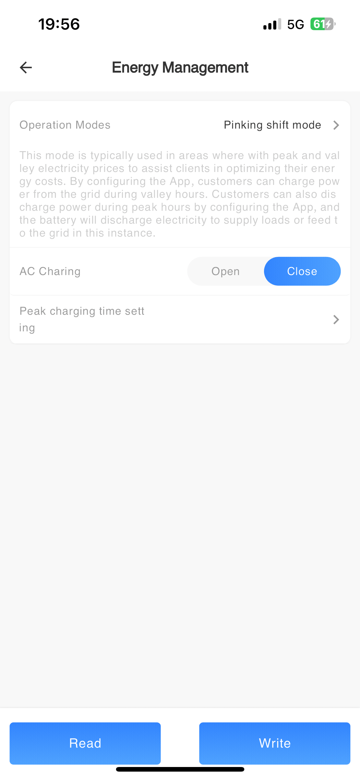
# Energy Management
| Parameter Name | Parameter Description | Parameter Range |
|---|---|---|
| Energy allocation mode | Select inverter operating mode | Off-grid Mode UPS Mode Self-generating-and-use Mode Peaking shift Mode Electricity sales mode Internal CT anti backflow External CT anti backflow |
| Forced Charging time setting | The machine works according to the set parameters such as the forced charging time period | |
| AC Charging | After being turned on, the power grid can charge the battery | Open/Close |
| AC Charging time setting | The machine works according to the set parameters such as AC charging time period | |
| Charge/Discharge time setting in Peaking shift Mode | The machine works according to the set parameters such as peak shaving charging or discharging time period | |
| PV energy supply priority setting | Set the priority of energy flow for photovoltaic power generation |
Load - Battery - Grid Load-Grid-Battery Battery - Load - Grid Connection |
| Peak shaving of power grid | Enable the grid peak shaving function after activation | Open/Close |
| Peak shaving power of power grid (W) | Limit the power supply from the power grid | Minimum setting 0, minimum unit 1kW |
| Zero output power (W) | Output power to the grid is zero | Minimum setting 0, minimum unit 1kW |
| Timed charging and discharging | After setting up, support the power grid or generator to charge the battery, and when the battery discharges to supply power to the load | Open/Close |
| Charging and discharging time setting | The machine charges or discharges the battery according to the set charging and discharging time period | |
| Charging switch | After enabling, the battery can be charged (1. There is PV for direct charging; 2. Preconditions for grid charging) | On/Off |
| Main grid switch | After enabling, the machine and battery are connected to the grid (a prerequisite for battery connection) | On/Off |
| Battery grid switch | After enabling, the main grid switch is also enabled, and the machine battery can be connected to the grid | On/Off |
| Maximum photovoltaic power(W) | ||
| Maximum photovoltaic selling power(W) | ||
| Photovoltaic electricity sales(Zero Export to Load) | ||
| Photovoltaic electricity sales(Zero Export to CT) |
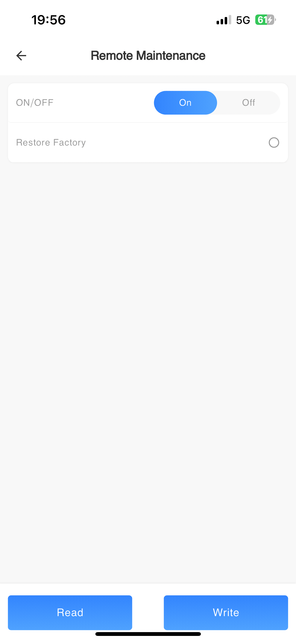
# Remote Maintenance
| Parameter Name | Parameter Description | Parameter Range |
|---|---|---|
| ON/OFF | Default enable, i.e. power on state, disable to enter standby state | Power on/off |
| Restart | After enabling, the machine will restart | Open/Close |
| Measurement Selection | Set according to the actual time in the country/region where the device is located |
Nothing Meter CT |
| CT Auto-Test Enable | After enabling, the CT direction can be set | Open/Close |
| R.CT direction setting | After enabling, perform reverse connection judgment under the condition of battery grid connection. If there is an abnormality, an error message will be given, and the correct CT direction can be manually set | Normal/Reverse |
| S.CT direction setting | After enabling, perform reverse connection judgment under the condition of battery grid connection. If there is an abnormality, an error message will be given, and the correct CT direction can be manually set | Normal/Reverse |
| T.CT direction setting | After enabling, perform reverse connection judgment under the condition of battery grid connection. If there is an abnormality, an error message will be given, and the correct CT direction can be manually set | Normal/Reverse |
| External CT transformation ratio | The transformation ratio is determined by the external CT | |
| R phase external CT enable | After enabling, the CT direction can be set | |
| Electricity meter brand and agreement | The corresponding electric meter brand when connecting an external electric meter | |
| Restore Factory | After enabling, all settings of the machine are restored to factory settings | Open/Close |
| S phase external CT enable | After enabling, the CT direction can be set | |
| T phase external CT enable | After enabling, the CT direction can be set | |
| Manually set the R-phase CT phase sequence | ||
| Manually set the S-phase CT phase sequence | ||
| Manually set the T-phase CT phase sequence | ||
| Electricity meter enable | ||
| Meter type | ||
| Inverter waiting for restart delay time(s) |
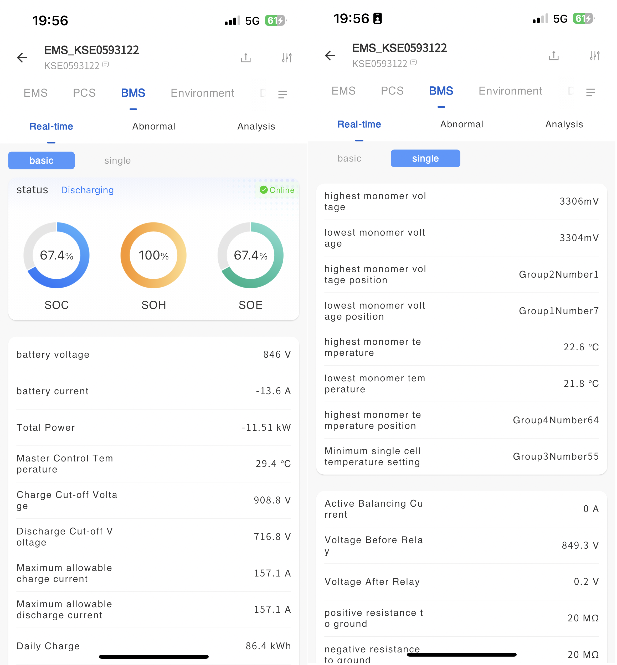
# BMS monitoring
Real-time information
The BMS real-time information page displays detailed operational data of the batteries in the cabinet, such as basic operational information, operational status, individual cell operational information, and detailed operational data of individual cells.
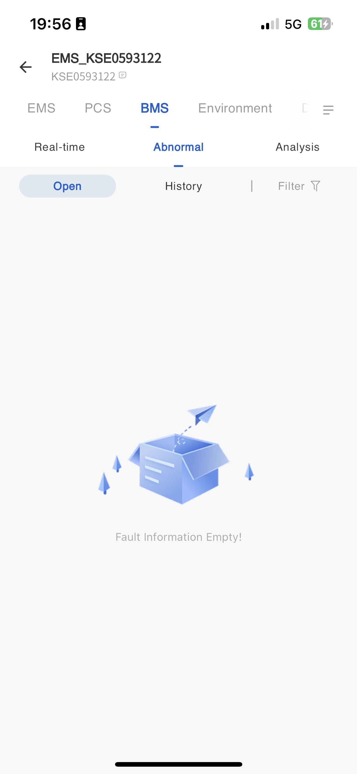
Fault information
In the fault information page, display all fault data of the BMS equipment. Move thebutton next to the mouse fault type to view the troubleshooting plan for the fault alarm.
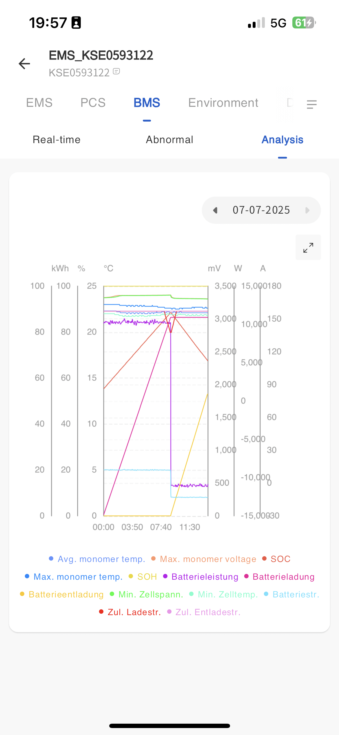
Statistical analysis
The statistics page displays the average temperature and maximum voltage of the BMS device as of the current time in the form of a line chart SOC、 Maximum monomer temperature SOH、 You can choose to view the operating data of any day, including battery power, charging capacity, discharging capacity, minimum cell voltage, minimum cell temperature, battery current, etc. You can also export it as a table for viewing.
Parameter configuration
The operation of remotely reading and setting the working parameters of BMS equipment.
| Parameter Name | Parameter Description | Parameter Range |
|---|---|---|
| Working mode | Normal mode/tooling testing mode | |
| Parameter processing | Clear running parameters Restore factory parameters Save alarm parameters to FLASH Report the calibration coefficient to FLASH Save parameters to FLASH Clear the lock fault | |
| Time setting |
Firmware Upgrade
The system supports remote upgrading of BMS firmware versions. You can upgrade the BMS firmware version in the cabinet through the following steps on the BMS monitoring page.
① Click on the power station - Power Station Management - Power Station List to enter the power station details.
② Click on [Device Monitoring] on the left to enter the list of energy storage unit devices.
③ Click on Energy Storage Unit Data - BMS Monitoring
④ Click the [Upgrade] button in the upper right corner and select the firmware version to upgrade from the pop-up firmware selection page.
⑤ After the system upgrade is completed, the new version of BMS can be used.
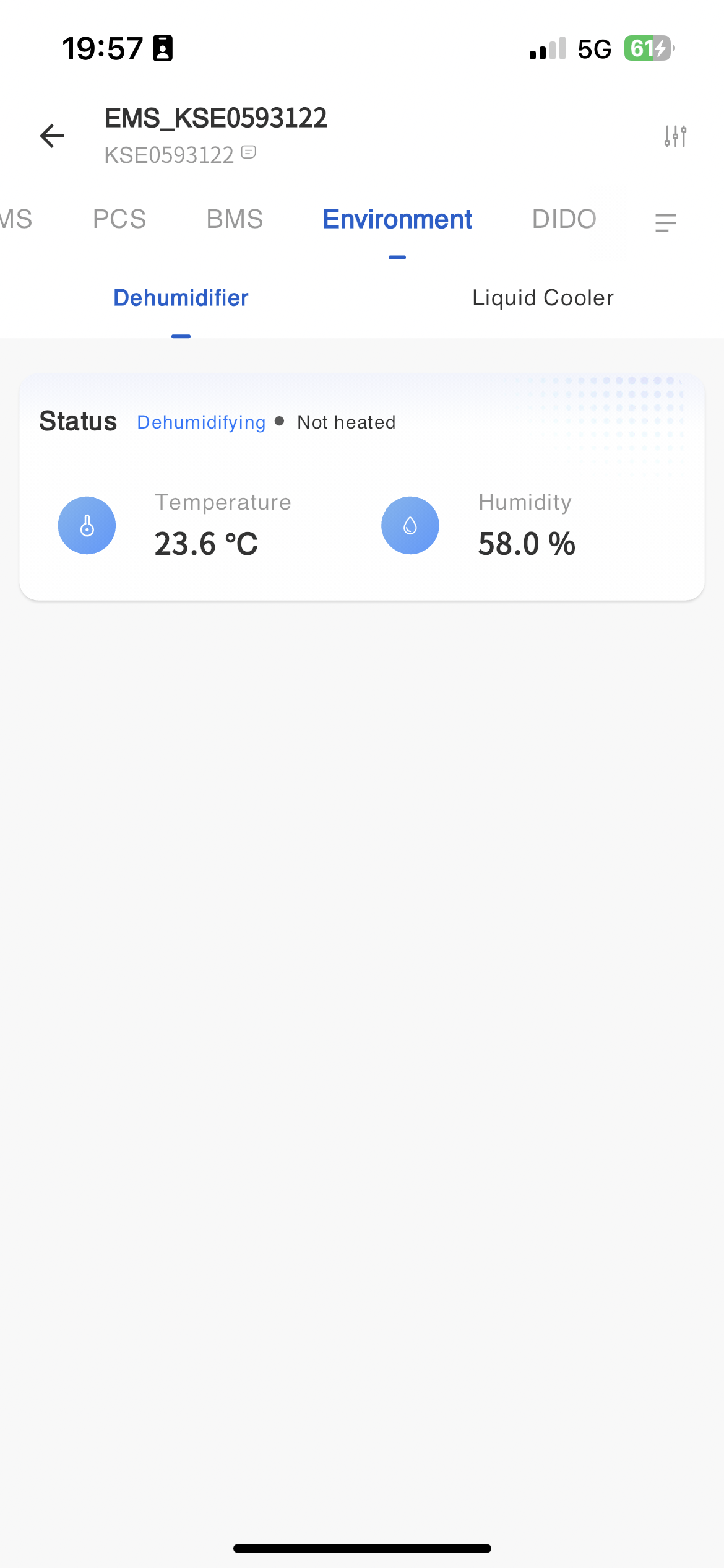
# Environmental monitoring
Dehumidifier operation data
The system displays the basic operating information of the dehumidifier on the environmental monitoring page, which you can view on this page.
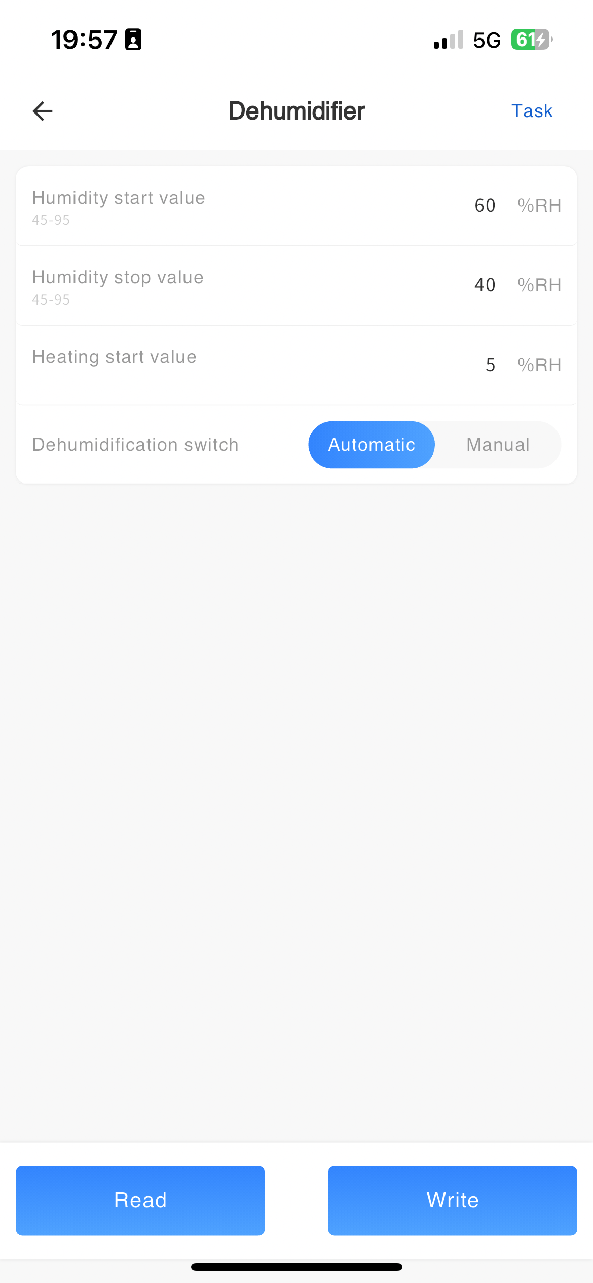
Dehumidifier parameter configuration
Remote reading and setting of dehumidifier parameters.
| Parameter Name | Parameter Description | Parameter Range |
|---|---|---|
| Temperature start-up value | Normal mode/tooling testing mode | |
| Temperature stop value | ||
| Heating start value | ||
| Dehumidification hand automatic switching |
Manual Automatic |
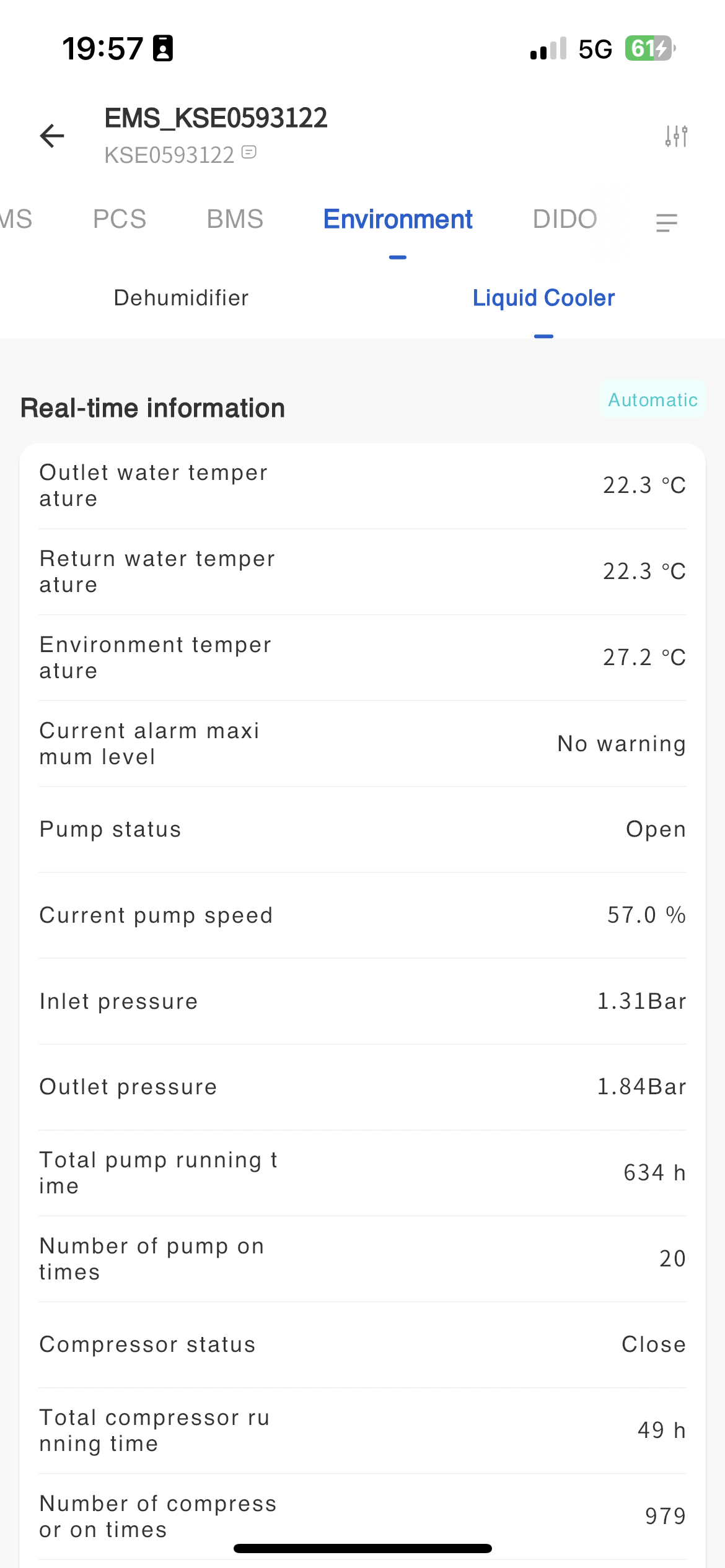
Operation data of liquid cooler
The system displays the basic operating information of the liquid cooler on the environmental monitoring page, which you can view on this page.
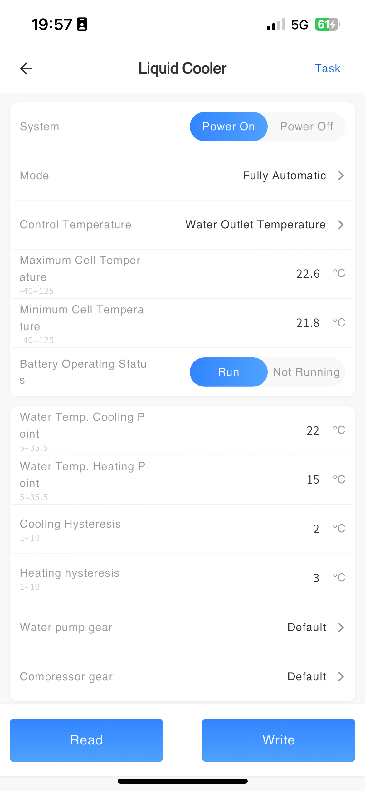
Parameter configuration of liquid cooler
Remote reading and setting of parameters for the liquid cooling machine.
| Parameter Name | Parameter Description | Parameter Range |
|---|---|---|
| System Switches | ||
| Mode Settings | ||
| Control temperature selection | ||
| Battery maximum temperature |
Manual Automatic | |
| Battery minimum temperature | ||
| Battery status | ||
| Water temperature cooling point | ||
| Water temperature heating point | ||
| Refrigeration Difference | ||
| Heating Difference | ||
| Cell temperature cooling stop point | ||
| Cell temperature heating point | ||
| Cell temperature heating stop point | ||
| Battery stationary temperature cooling point | ||
| Cell temperature self-cycle start deviation | ||
| Cell temperature self-cycle stop poor | ||
| Battery Allowed Minimum Temperature | ||
| Battery Allowed Maximum Temperature | ||
| Silent mode enables switching | ||
| Silent mode fan speed limit |
# EMS monitoring
The system displays the communication status between devices and servers on the EMS monitoring page, as well as the communication status between PCS, BMS, dehumidifiers, and liquid coolers and EMS devices.
# ETU monitoring
The system displays the communication status between devices and servers on the ETU monitoring page, as well as the communication status between PCS, BMS, dehumidifiers, and liquid coolers and ETU devices. The display content on the ETU device and EMS device pages is the same, but they belong to different machines
ETU parameter configuration
You can set the parameters for voltage regulation and intelligent power protection in the ETU parameter configuration. The parameters that can be set are as follows:
Voltage regulation setting
| Parameter Name | Parameter Description | Parameter Range |
|---|---|---|
| ETU mode selection | ||
| Active voltage sensitivity coefficient | ||
| Active voltage sensitivity coefficient | ||
| Voltage regulation hysteresis voltage | ||
| Voltage regulation dead zone lower limit | ||
| Voltage regulation dead zone upper limit | ||
| Mandatory Battery Recharge Power | ||
| Battery regulation cycle | ||
| Cq calculates the upper limit of reactive power |
Energy management
| Parameter Name | Parameter Description | Parameter Range |
|---|---|---|
| Energy distribution mode | ||
| Intelligent power supply | ||
| Smart Power Protection SOC | ||
| Intelligent power saving | ||
| Forced power supply | ||
| Forced power failure time |
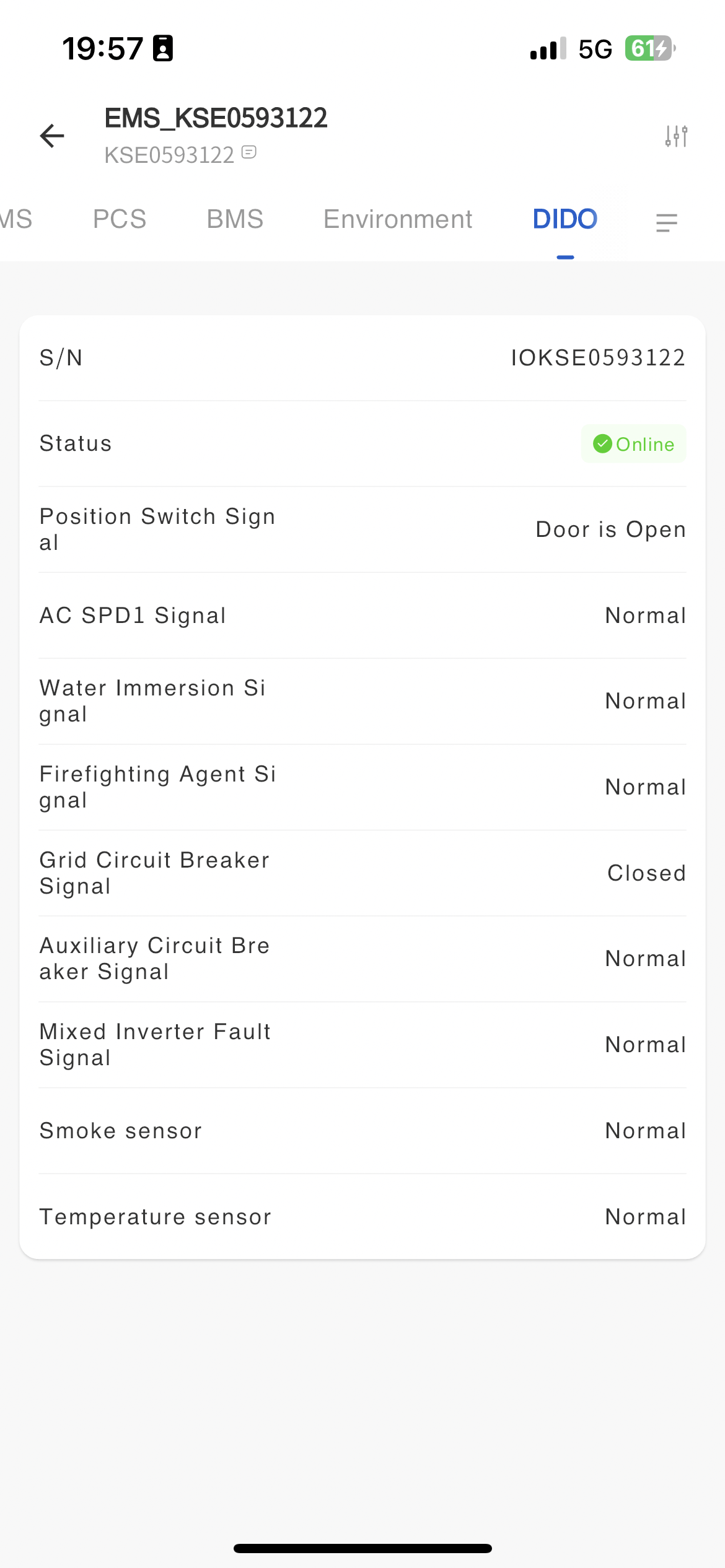
# DIDO
You can view the operation status of the device on the DIDO page,
DIDO parameter settings
At present, only industrial and commercial storage cabinets are supported for parameter settings. The DIDO function of energy storage and voltage regulation cabinets is limited and does not support parameter settings. The specific parameters that can be set are as follows:

| Parameter Name | Parameter Description | Parameter Range |
|---|---|---|
| Cabinet door light panel | ||
| Inverter stop operation control |
# Air conditioning monitoring
You can view the working condition and status of the air conditioning in the cabinet on the air conditioning monitoring page.
Air conditioning parameter configuration
| Parameter Name | Parameter Description | Parameter Range |
|---|---|---|
| Cooling Point | ||
| Refrigeration Difference | ||
| Heating point | ||
| Heating Difference | ||
| Dehumidification point | ||
| Dehumidification Difference | ||
| High temperature | ||
| Low Temperature Point | ||
| High humidity | ||
| Indoor Fan Stop Point | ||
| Maximum control temperature | ||
| Minimum control temperature | ||
| Temperature control | ||
| Monitoring switch | ||
| Start cooling command | ||
| Start air supply cooling | ||
| Start Standby Command | ||
| Start heating and cooling |
# Beidou positioning monitoring
You can view the current location of the cabinet and the working status of the Beidou equipment on the Beidou positioning monitoring page.
Beidou parameter setting
| Parameter Name | Parameter Description | Parameter Range |
|---|---|---|
| From Station Address | ||
| Porter Rate | ||
| Parity Check | ||
| Positioning mode | ||
| Frequency of updates |
# Voltage regulation statistics
You can view the total voltage regulation data and regulation time data of the cabinet on the voltage regulation statistics page, which is convenient for you to understand the voltage regulation work of the machine.
# CO monitoring
You can view the working status and data of the CO monitor on the CO monitoring page, which facilitates your understanding of the machine's working condition.
CO monitoring parameter settings
| Parameter Name | Parameter Description | Parameter Range |
|---|---|---|
| Power mode |