# Equipment configuration
This system supports reading or setting device operating parameters in the data list of the device module.
# Global configuration steps
① Log in to the Smart M app.
② Click on [Device] at the bottom to enter the data list page.
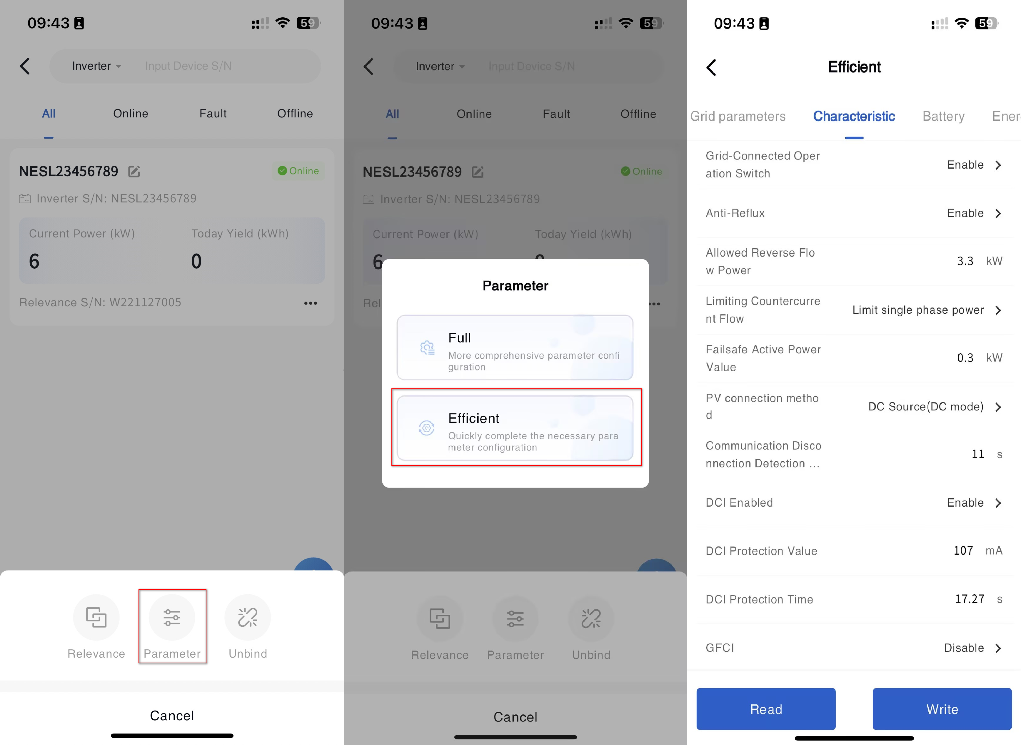
③ Click the [...] - [Configure] button on the right side. (If the device model supports quick configuration, clicking the configuration button will bring up a configuration mode selection pop-up window. If quick configuration is not supported, the page will directly enter the parameter configuration page.)
④ Select Global Configuration in the pop-up configuration mode selection window.
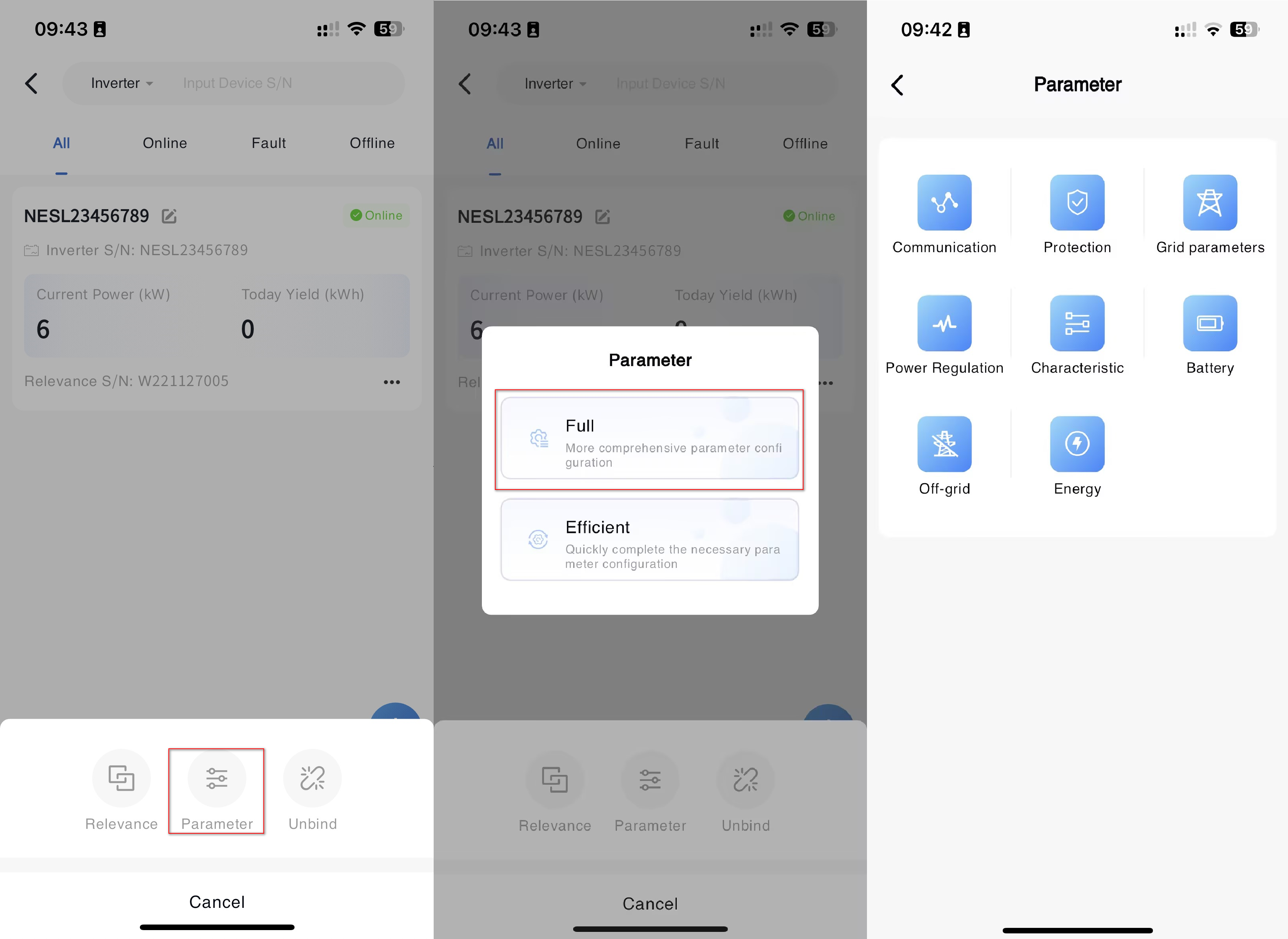
⑤ In the pop-up parameter configuration page, select the type of parameter that needs to be set.
⑥ In the corresponding parameter type input box, enter the parameter value that needs to be modified, and click the [Settings] button.
# Communication
| Parameter Name | Parameter Description | Parameter Range |
|---|---|---|
| Server address | The data communication transmission address of the collector. | |
| Server Port | The service transmission port for data communication of the collector. | |
| Collector system time | Set according to the actual time in the country/region where the device is located |
# Grid

| Parameter Name | Parameter Description | Parameter Range |
|---|---|---|
| Country | Setting different countries, regulations will display corresponding content | |
| Standard | After setting regulations, relevant information such as grid connection parameters, protection&time, etc. will be automatically modified to the corresponding regulatory settings. | |
| Auto Test | Used to check and verify the operational status, performance, and safety of inverters. When choosing Italy as the country, the Auto Test function can be used |
# On-Grid
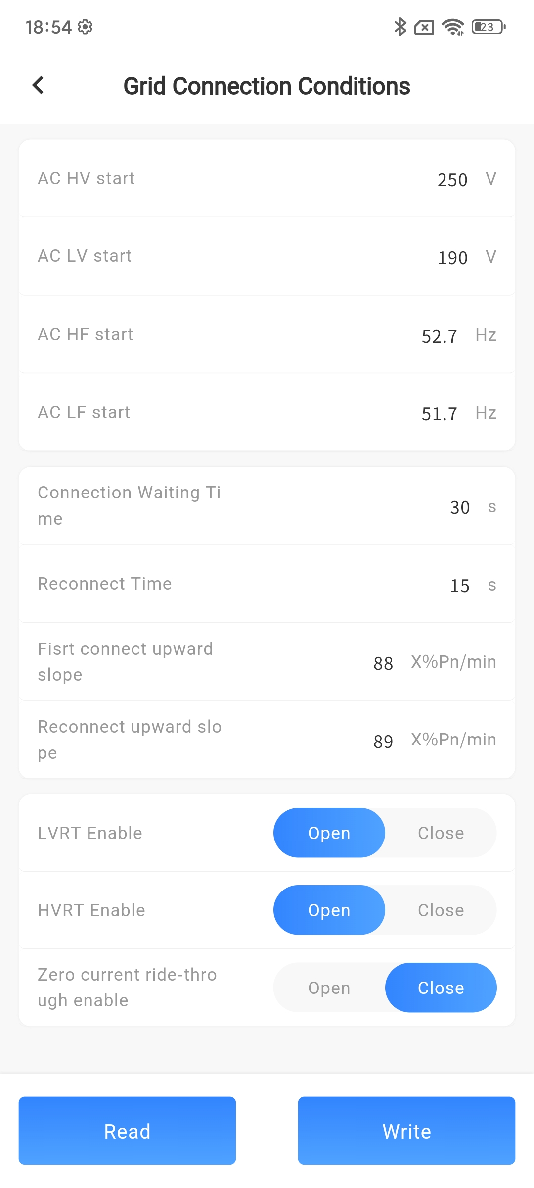
On-Grid conditions
| Parameter Name | Parameter Description | Parameter Range |
|---|---|---|
| AC HV start (V) | The highest mains voltage that a machine can connect to the grid. If the machine detects that the mains voltage exceeds this voltage before grid connection, it will not be able to connect to the grid (the regulations will be automatically modified to the corresponding regulatory settings, and it is not recommended for users to modify) | 100V-600V,minimum unit 0.1V |
| AC LV start (V) | The minimum mains voltage at which a machine can connect to the grid. If the machine detects that the mains voltage is lower than this voltage before grid connection, it will not be able to connect to the grid (the regulations will be automatically modified to the corresponding regulatory settings, and it is not recommended for users to modify) | 100V-600V,minimum unit 0.1V |
| AC HF start (Hz) | The highest mains frequency at which a machine can connect to the grid. If the machine detects that the mains frequency exceeds this frequency before grid connection, it will not be able to connect to the grid (the regulations will be automatically modified to the corresponding regulatory settings, and it is not recommended for users to modify) | 45Hz-65Hz,minimum unit 0.01Hz |
| AC LF start (Hz) | The minimum mains frequency at which a machine can connect to the grid. If the machine detects that the mains voltage is lower than this frequency before grid connection, it will not be able to connect to the grid (the regulations will be automatically modified to the corresponding regulatory settings, and it is not recommended for users to modify) | 45Hz-65Hz,minimum unit 0.01Hz |
| Connection Waiting Time (s) | The waiting time before the first grid connection after the machine is turned on (setting regulations will automatically modify to the corresponding regulatory settings, and it is not recommended for users to modify) | 1-65535s, minimum 1s |
| Reconnect Time (s) | The waiting time before the machine is reconnected to the grid due to standby or disconnection from the mains power, etc. (The setting of regulations will automatically modify to the corresponding regulatory setting value, and it is not recommended for users to modify it) | 1-65535s, minimum 1s |
| First connect upward slope (% Pn/min) | The rate at which the machine tracks to the maximum power point of MPPT after being connected to the grid for the first time after startup (the setting of regulations will automatically modify to the corresponding regulatory setting value, and it is not recommended for users to modify it) | 1-65535,minimum unit 1X%Pn/min |
| Reconnect upward slope (% Pn/min) | The rate at which the machine tracks to the maximum power point of MPPT after reconnecting to the grid (setting regulations will automatically modify to the corresponding regulatory setting value, it is not recommended for users to modify) | 1-65535,minimum unit 1X%Pn/min |
| LVRT Enable | Enable low voltage ride through function after activation | Open/Close |
| HVRT Enable | Enable high voltage ride through function after activation | Open/Close |
| Zero current ride through enable | Enable zero current ride through function after activation | Open/Close |
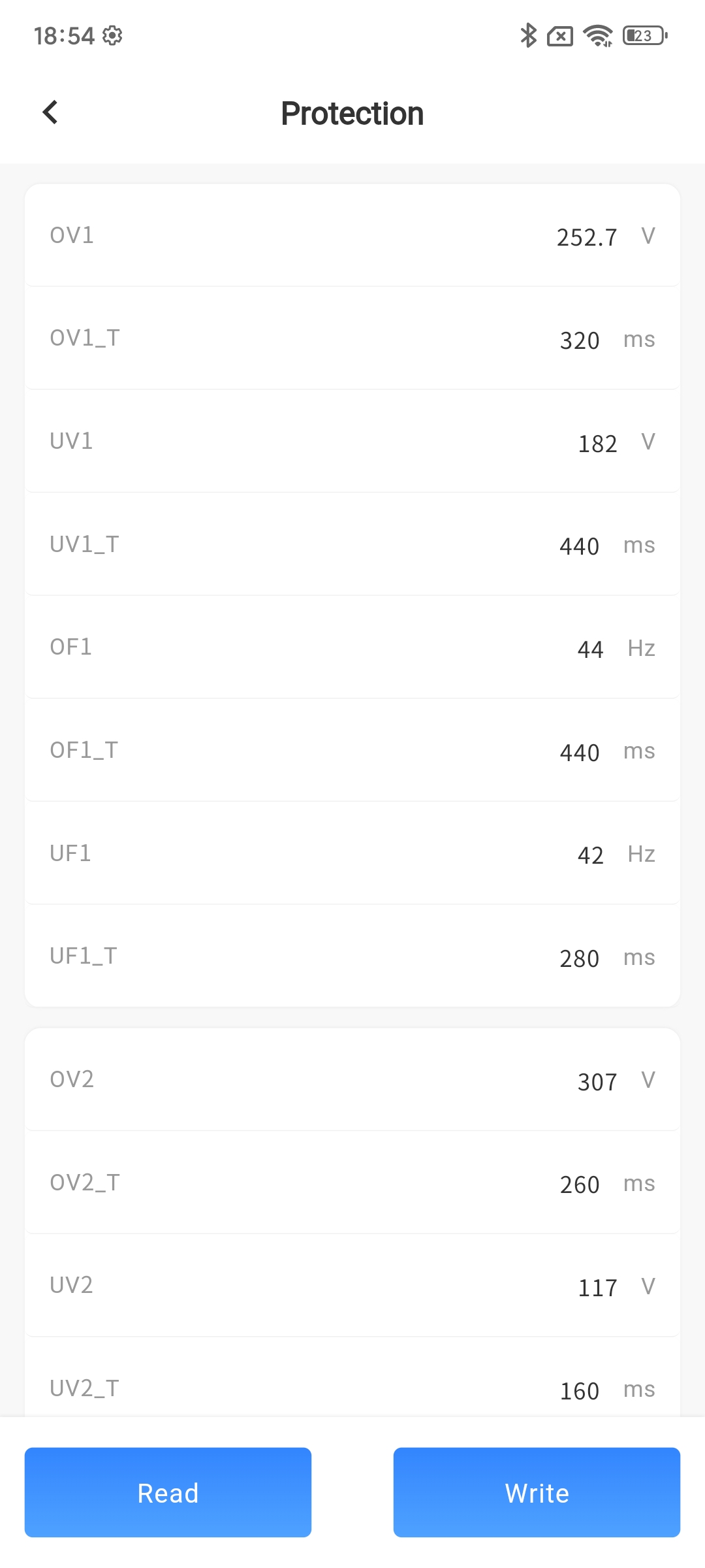
Protection & Time
| Parameter Name | Parameter Description | Parameter Range |
|---|---|---|
| UV1 (V) | When the machine detects that the mains voltage is too low, it will protect and report a level 1 undervoltage fault (the setting regulations will automatically modify to the corresponding regulatory setting values, and it is not recommended for users to modify) | Minimum setting 0, minimum unit 0.1V |
| OV1(V) | When the machine detects that the mains voltage is too high, it will protect and report a level 1 overvoltage fault (the setting regulations will automatically modify to the corresponding regulatory setting values, and it is not recommended for users to modify) | Minimum setting 0, minimum unit 0.1V |
| UF1(Hz) | When the machine detects that the mains frequency is low to this frequency, it will protect and report a level 1 underfrequency fault (setting regulations will automatically modify to the corresponding regulatory setting value, it is not recommended for users to modify) | Minimum setting 0, minimum unit 0.01Hz |
| OF1(Hz) | When the machine detects that the mains frequency is too high at this frequency, it will protect and report a level 1 overclocking fault (setting regulations will automatically modify to the corresponding regulatory setting value, it is not recommended for users to modify) | Minimum setting 0, minimum unit 0.01Hz |
| UV1_T(ms) | The time taken from level 1 undervoltage of the mains power to machine protection (setting regulations will automatically modify to the corresponding regulatory setting value, it is not recommended for users to modify) | Minimum setting 0, minimum unit 20ms |
| OV1_T(ms) | The time taken from level 1 overvoltage of the mains power to machine protection (the setting of regulations will automatically modify to the corresponding regulatory setting value, and it is not recommended for users to modify) | Minimum setting 0, minimum unit 20ms |
| UF1_T(ms) | The time taken from underfrequency at level 1 of the municipal power supply to machine protection (setting regulations will automatically modify to the corresponding regulatory settings, and it is not recommended for users to modify) | Minimum setting 0, minimum unit 20ms |
| OF1_T(ms) | The time taken from level 1 overclocking of the mains power to machine protection (setting regulations will automatically modify to the corresponding regulatory setting value, and it is not recommended for users to modify) | Minimum setting 0, minimum unit 20ms |
| UV2(V) | When the machine detects that the mains voltage is too low, it will protect and report a level 2 undervoltage fault (the setting regulations will automatically modify to the corresponding regulatory setting values, and it is not recommended for users to modify) | Minimum setting 0, minimum unit 0.1V |
| OV2(V) | When the machine detects that the mains voltage is high enough, it will protect and report a level 2 overvoltage fault (the setting regulations will automatically modify to the corresponding regulatory setting values, and it is not recommended for users to modify) | Minimum setting 0, minimum unit 0.1V |
| UF2(Hz) | When the machine detects that the mains frequency is low to this frequency, it will protect and report a level 2 underfrequency fault (setting regulations will automatically modify to the corresponding regulatory setting value, it is not recommended for users to modify) | Minimum setting 0, minimum unit 0.01Hz |
| OF2(Hz) | When the machine detects that the mains frequency is too high at this frequency, it will protect and report a level 2 overclocking fault (setting regulations will automatically modify to the corresponding regulatory setting value, it is not recommended for users to modify) | Minimum setting 0, minimum unit 0.01Hz |
| UV2_T(ms) | The time taken from under voltage at level 2 of the mains power supply to machine protection (the setting of regulations will automatically modify to the corresponding regulatory setting value, and it is not recommended for users to modify it) | Minimum setting 0, minimum unit 20ms |
| OV2_T(ms) | The time taken from overvoltage level 2 of the mains power to machine protection (setting regulations will automatically modify to the corresponding regulatory setting value, it is not recommended for users to modify) | Minimum setting 0, minimum unit 20ms |
| UF2_T(ms) | The time taken from underfrequency at level 2 of the mains power to machine protection (setting regulations will automatically modify to the corresponding regulatory settings, and it is not recommended for users to modify) | Minimum setting 0, minimum unit 20ms |
| OF2_T(ms) | The time taken from overclocking at level 2 of the mains power to machine protection (setting regulations will automatically modify to the corresponding regulatory settings, and it is not recommended for users to modify) | Minimum setting 0, minimum unit 20ms |
| UV3(V) | When the machine detects that the mains voltage is too low, it will protect and report a level 3 undervoltage fault (the setting regulations will automatically modify to the corresponding regulatory setting values, and it is not recommended for users to modify) | Minimum setting 0, minimum unit 0.1V |
| OV3(V) | When the machine detects that the mains voltage is high enough, it will protect and report a level 3 overvoltage fault (the setting regulations will automatically modify to the corresponding regulatory setting values, and it is not recommended for users to modify) | Minimum setting 0, minimum unit 0.1V |
| UF3(Hz) | When the machine detects that the mains frequency is low to this frequency, it will protect and report a level 3 underfrequency fault (setting regulations will automatically modify to the corresponding regulatory setting value, it is not recommended for users to modify) | Minimum setting 0, minimum unit 0.01Hz |
| OF3(Hz) | The machine detects that the mains frequency is too high and will protect it, reporting a level 3 overclocking fault (setting regulations will automatically modify to the corresponding regulatory setting value, it is not recommended for users to modify) | Minimum setting 0, minimum unit 0.01Hz |
| UV3_T(ms) | The time taken from level 3 undervoltage of the mains power to machine protection (setting regulations will automatically modify to the corresponding regulatory setting value, it is not recommended for users to modify) | Minimum setting 0, minimum unit 20ms |
| OV3_T(ms) | The time taken from level 3 overvoltage of the mains power to machine protection (setting regulations will automatically modify to the corresponding regulatory setting value, and it is not recommended for users to modify) | Minimum setting 0, minimum unit 20ms |
| UF3_T(ms) | The time taken from underfrequency at level 3 of the mains power to machine protection (setting regulations will automatically modify to the corresponding regulatory settings, and it is not recommended for users to modify) | Minimum setting 0, minimum unit 20ms |
| OF3_T(ms) | The time taken from overclocking at level 3 of the mains power to machine protection (setting regulations will automatically modify to the corresponding regulatory settings, and it is not recommended for users to modify) | Minimum setting 0, minimum unit 20ms |
| 10 min OV Protection(V) | When the grid voltage exceeds 1.1 times, the inverter should operate for at least 10 minutes (conflicting with the overvoltage protection function, which requires setting the overvoltage protection time to be greater than 10 minutes) | Minimum setting 0, minimum unit 0.1V |
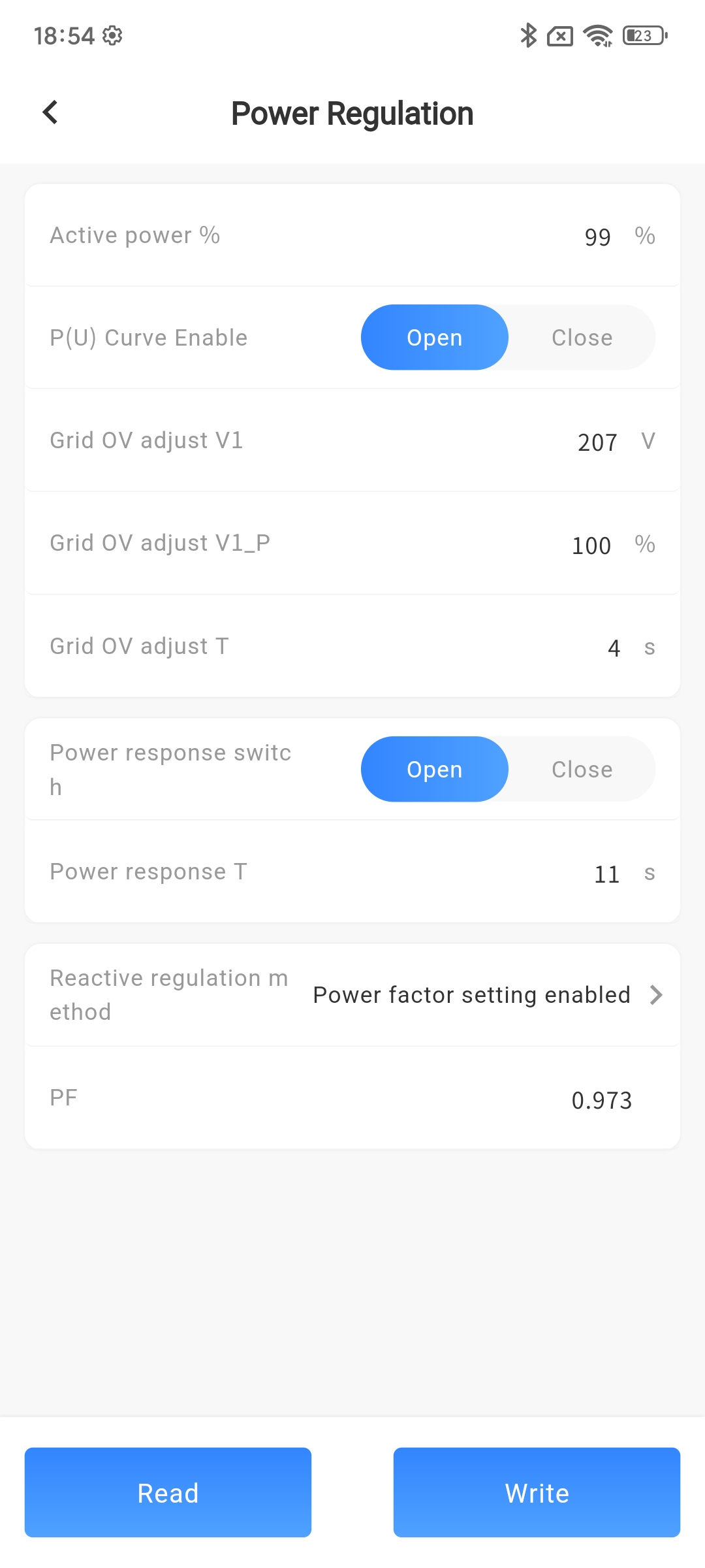
Power
| Parameter Name | Parameter Description | Parameter Range |
|---|---|---|
| Active power % | After setting the value, the maximum power of the machine becomes the maximum power multiplied by the set percentage | Minimum setting 0, minimum unit 0.1% |
| P(U) Curve Enable | After setting, the machine works according to the P (U) curve | Open/Close |
| V1 (V) | After setting the value, the equipment adjusts to the voltage value after the power grid is overvoltage | Minimum setting 0, minimum unit 0.1V |
| V1_P (%) | After setting the value, the equipment adjusts the power to the value after overvoltage in the power grid | Minimum setting 0, minimum unit 0.1% |
| T (s) | After setting the value, the equipment will automatically adjust after experiencing the overvoltage of the power grid for a certain period of time | Minimum setting 0, minimum unit 1s |
| Power response switch | After enabling, the reactive power response speed can be set, otherwise it will respond at the fastest speed | Open/Close |
| T (s) | Set reactive power response time constant | |
| Reactive regulation method | The specific standards supported by the device under the national/regional power grid should be selected based on the current grid standards connected to the device. | Disable PE Enable Reactive power % Enable Q (U) curve can be set Q (P) curve can be set |
| Reactive power % (%) | Reactive power percentage can be set | Minimum setting 0, minimum unit 0.1% |
| power factor | Power factor value can be set | Minimum setting 0, minimum unit 0.001 |
| Q(P) Curve Type | Q (P) curve can be set |
CurveA CurveB CurveC |
| Q(U) Curve Type | Q (U) curve can be set |
CurveA CurveB CurveC |
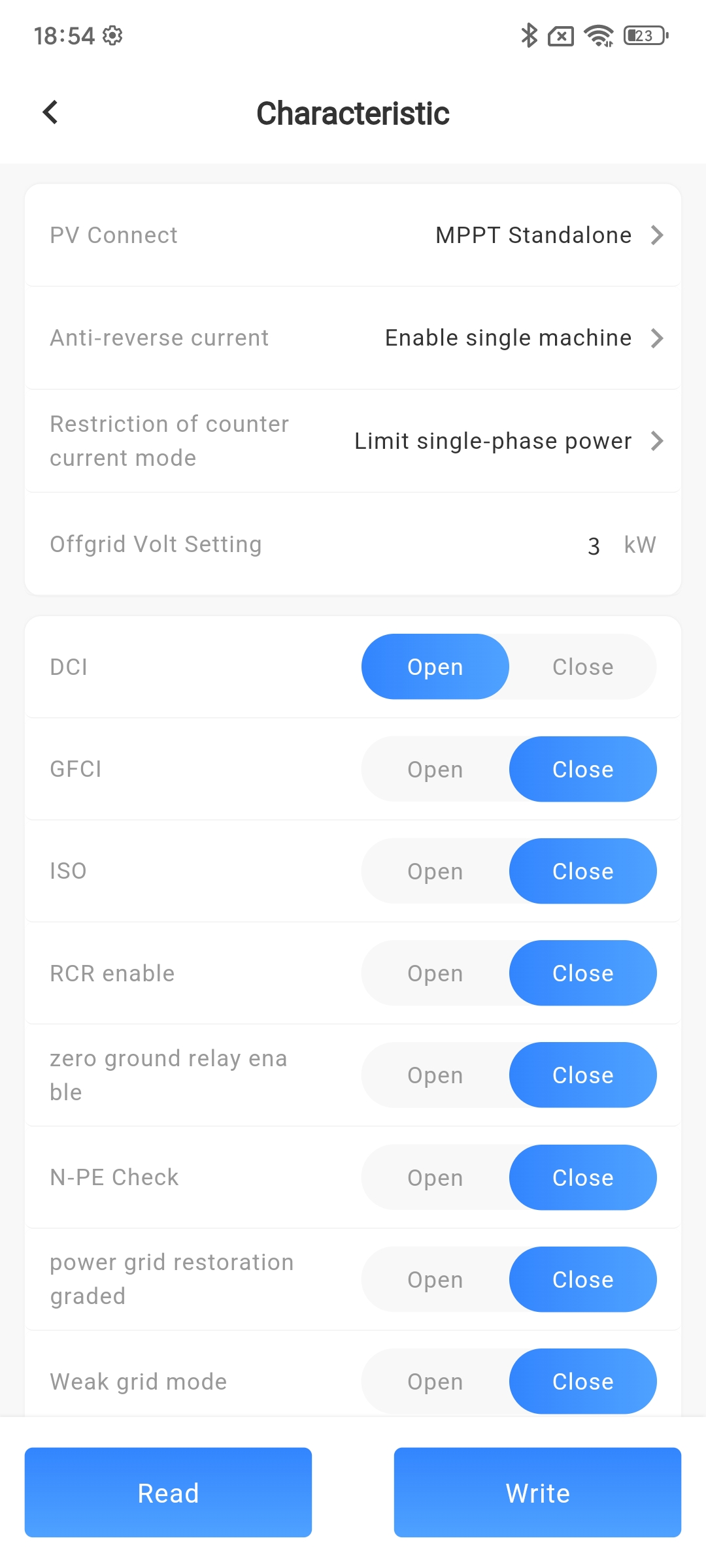
# Characteristic
| Parameter Name | Parameter Description | Parameter Range |
|---|---|---|
| PV Connect | Independent parallel DC source mode selection | MPPT Standalone MPPT Parallel DC Source | Anti-reverse current | After turning on, the machine delivers energy to the mains side at the set power. | Open/Close |
| Allowable reverse current power (kW) | The first level allows for the triggering and judgment time of reverse power protection. | 0-6553.5kW, minimum unit 0.1kW |
| Restricting countercurrent methods | Choose the method of limiting device power, and before setting it, please confirm whether the device supports this method. | Limit three-phase total power/limit individual power |
| DCI | DCI stands for DC component, and when turned on, the machine will control the DC component on the grid side within the regulatory allowable range. | Open/Close |
| GFCI | Leakage current detection protection, the machine will protect when the leakage current exceeds the safe range | Open/Close |
| ISO | Insulation impedance testing, which will be conducted by the machine during grid connection testing after enabling. | Open/Close |
| N-PE Check | After turning on, the machine will check if the N-PE connection is normal, and if there are any abnormalities, it will sound an alarm. | Open/Close |
| Zero ground relay enable | When there is an abnormal communication between the online electricity meter and the inverter, the active power limit of the inverter can be manually adjusted by the customer as needed. | Open/Close |
| Power grid restoration with gradual change in power | Set the detection time for communication disconnection failure protection between the inverter and the data stick. | Open/Close |
| Weak grid mode | Suitable for three-phase three wire system or three-phase four wire system. | Open/Close |
| Zero current mode | After enabling, the machine can perform high and low voltage crossing at zero current. | Open/Close |
| DC lightning protection detection | DC component protection value. | Open/Close |
| RCR | RCR enabled, can control the percentage of active power when turned on | Open/Close |
| Island | After activation, the machine can quickly identify and exit the grid connection when it enters an isolated state | Open/Close |
| DRM | DRM enabled, can control the percentage of active power when turned on | Open/Close |
| AFCI | After enabling, the device starts arc detection | Open/Close |
| Backup ON/OFF | By default, it is turned off. After being turned on, the machine can back up for voltage output during the set off grid time period | Open/Close |
| Backup time setting | Communication speed connected to the upper computer | |
| Offgrid Volt Setting (V) | The off grid side output voltage can be modified. When the machine is off grid, the back up output is the off grid voltage setting value, and when connected to the grid, the back up output is the mains input voltage | Minimum setting 0, minimum unit 0.1V |
| Offgrid Freq Setting (Hz) | The off grid side output frequency can be modified. When the machine is off grid, the back up output is the off grid frequency setting value, and when connected to the grid, the back up output is the mains input frequency | Minimum setting 0, minimum unit 0.01Hz |
| Parallel | Enable parallel operation and disable single machine operation | Open/Close |
| Parallel address | No setting required, automatically retrieved from the device after enabling parallel operation | |
| master-slave setup | Choose whether the current connected device is a host or a slave based on the actual situation. | Host/Slave |
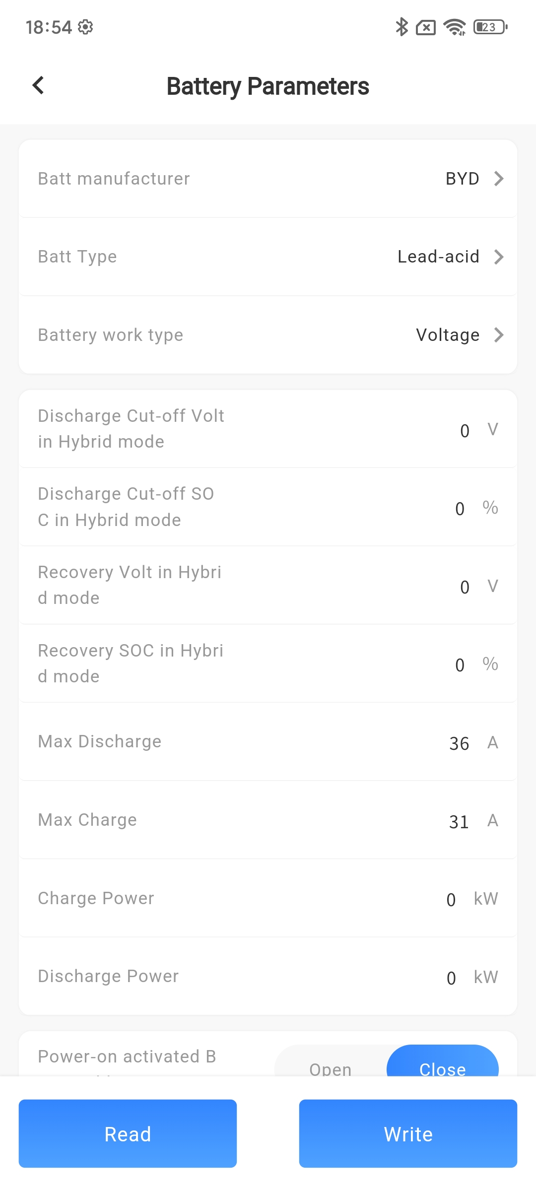
# Battery
| Parameter Name | Parameter Description | Parameter Range |
|---|---|---|
| Batt manufacturer | Set the manufacturer of the battery | Zhongxing Paineng_CAN Zhongxing Paineng_RS485 Tianbang Da_CAN Tianbang Da_RS485 Xinwangda_CAN Xinwangda_RS485 BYD_CAN BYD_RS485 Youneng_CAN Youneng_RS485 Jiabaida_CAN Jiabaida_RS485 AOBOET_CAN AOBOET_RS485 SLENERGY_CAN SLENERGY_RS485 DESAY_CAN DESAY_RS485 GENIXGEREEN_CAN GENIXGEREEN_RS485 DYNESS_CAN DYNESS_RS485 |
| Batt Type | Select the type of battery | No Batt/Lead-acid/Lithum |
| Battery operation type | Select battery operating mode | Voltage/SOC/No Batt |
| Discharge Cut-off Volt in Hybrid mode (V) | In the presence of PV, after setting the value, the battery voltage will stop discharging when it is lower than the set value | Minimum setting 0, minimum unit 0.1V |
| Discharge Cut-off SOC in Hybrid mode (%) | In the presence of PV, after setting the value, the battery will discharge until the SOC is lower than the set value, and then stop discharging | Minimum setting 0, minimum unit 1% |
| Recovery Volt in Hybrid mode (V) | In the presence of PV, after setting the value, discharging is allowed when the battery voltage is higher than the set value | Minimum setting 0, minimum unit 0.1V< |
| Recovery SOC in Hybrid mode (%) | In the presence of PV, after setting the value, the battery is allowed to discharge after charging to SOC higher than the set value | Minimum setting 0, minimum unit 1% |
| Max Discharge (A) | Set the maximum discharge current of the battery | Minimum setting 0, minimum unit 1A |
| Max Charge (A) | Set the maximum charging current of the battery | Minimum setting 0, minimum unit 1A |
| Charge Power (kW) | Set the maximum charging power of the battery | Minimum setting 0, minimum unit 0.1kW |
| Discharge Power (kW) | Set the maximum discharge power of the battery | Minimum setting 0, minimum unit 0.1kW |
| Power-on activated Batt enable | Enable and power on to activate the battery | Open/Close |
| Active Batt Enable | Activate the battery continuously after enabling | Open/Close |
| Charge Enable | After enabling, the battery can be charged (1. Direct charging with PV; 2. Preconditions for grid charging) | Open/Close |
| Grid-tie Enable | After enabling, the machine and battery are connected to the grid (a prerequisite for battery connection) | Open/Close |
| Batt Grid-tie Enable | After enabling, the main grid switch is also enabled, and the machine battery can be connected to the grid | Open/Close |
| AC Charging Max current (A) | Set the maximum charging current of the battery to the mains power supply | Minimum setting 0, minimum unit 1A |
| AC charging target SOC (%) | Set the SOC for charging the battery using mains power | Minimum setting 0, minimum unit 1% |
| AC charging target Volt (V) | Set the voltage for charging the battery using mains power | Minimum setting 0, minimum unit 0.1V |
| Battery capacity (Ah) | Set according to the actual installed battery capacity | Minimum setting 0, minimum unit 1Ah |
| Lithium battery loss report fault switch | After setting, if the battery BMS cannot communicate with the inverter, the inverter will stop working and report a fault | Open/Close |
| Discharge Cut-off Volt (V) | When the battery voltage is below this set threshold, the battery cannot generate electricity | Minimum setting 0, minimum unit 0.1V |
| Recovery Volt (V) | When the battery voltage exceeds the threshold set, the battery can be discharged | Minimum setting 0, minimum unit 0.1V |
| Discharge Cut-off SOC (%) | After setting the value, the battery will stop discharging when the SOC is lower than the set value | Minimum setting 0, minimum unit 1% |
| Recovery SOC (%) | After setting the value, the battery will resume discharging when the SOC is higher than the set value | Minimum setting 0, minimum unit 1% |
| Chai Fa Charging Switch | After setting up, use a generator to charge the connected battery pack | Open/Close |
| Diesel charging current (A) | Can set the generator to charge the battery current | Minimum setting 0, minimum unit 1A |
| Chai Fa Signal | Set the discharge power of the energy storage device. | Realy normally open/Relay closure |
| Diesel engine forced opening | When the generator is connected, it is forced to start the generator without meeting other conditions | Open/Close |
| AC Charge Enable | After setting up, use the power grid to charge the connected battery pack | Open/Close |
| Grid Charge Activation Volt (V) | When the battery voltage falls below this set threshold, the power grid begins to forcefully charge the battery | Minimum setting 0, minimum unit 0.1V |
| Grid Charge Activation SOC (%) | When the SOC of the battery falls below this set threshold, the power grid begins to forcibly charge the battery | Minimum setting 0, minimum unit 1% |
| Grid charging current (A) | Can set the charging current of the battery to the power grid | Minimum setting 0, minimum unit 1A |
| Power grid signal | Set the discharge power of the energy storage device. | Minimum 0, minimum unit 0.1kW |
| Float Volt (V) | Set the float charging voltage for lead-acid batteries | Minimum setting 0, minimum unit 0.1V |
| Absorption Volt (V) | Set the constant voltage charging voltage for lead-acid batteries | Minimum setting 0, minimum unit 0.1V |
| Balanced charging voltage (V) | Set the balanced charging voltage for lead-acid batteries | Minimum setting 0, minimum unit 0.1V |
| Balanced charging cycle (days) | Set the balanced charging cycle for lead-acid batteries | Minimum setting 0, minimum unit 1Day |
| Balanced charging duration (hours) | Set the balanced charging duration for lead-acid batteries | Minimum setting 0, minimum unit 1 hour |
| Under voltage alarm voltage (V) | Alarm lead-acid and lithium batteries when they reach the set voltage value | Minimum setting 0, minimum unit 0.1V |
| Under voltage alarm SOC (%) | Alarm lead-acid and lithium batteries when they reach the set SOC value | Minimum setting 0, minimum unit 1% |
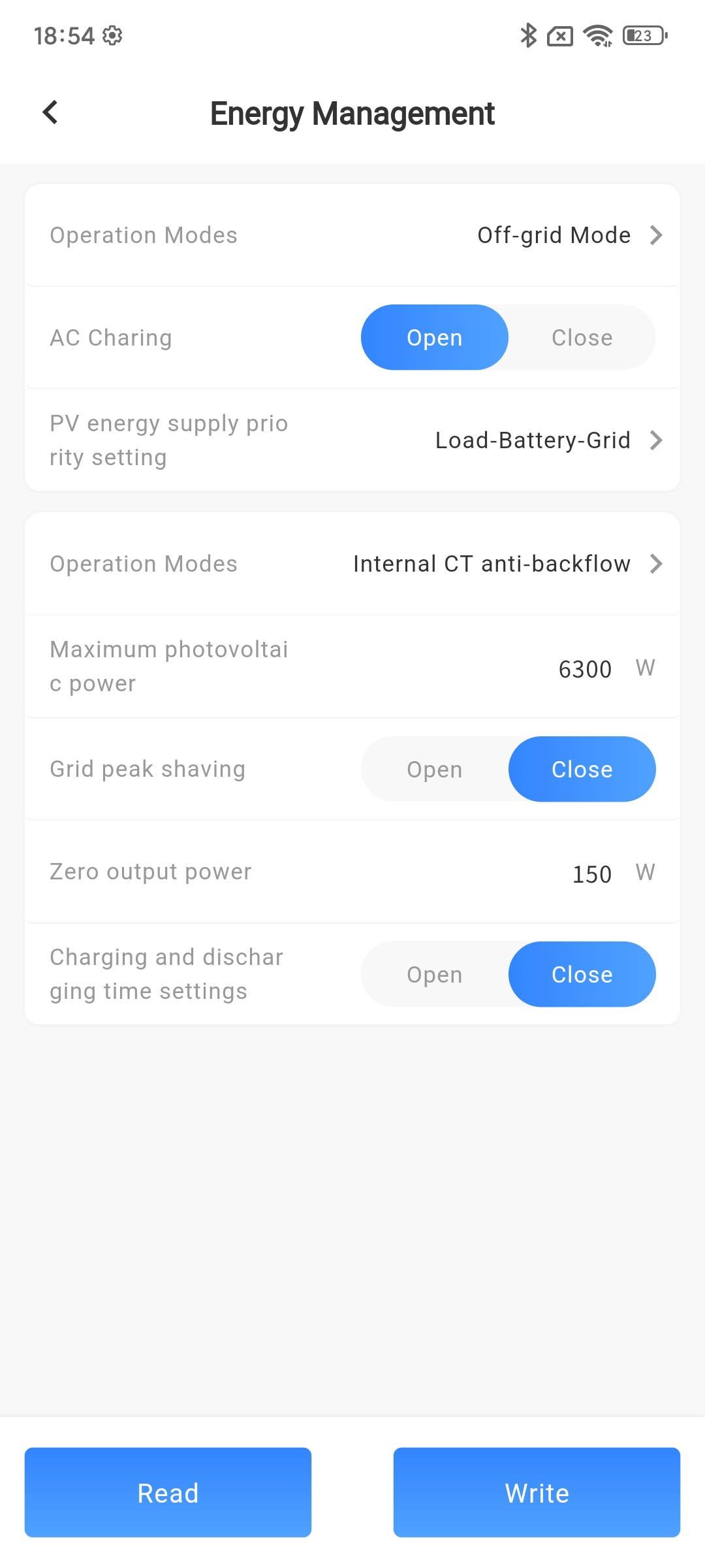
# Energy Management
| Parameter Name | Parameter Description | Parameter Range |
|---|---|---|
| Energy allocation mode | Select inverter operating mode | Off-grid Mode UPS Mode Self-generating-and-use Mode Peaking shift Mode Electricity sales mode Internal CT anti backflow External CT anti backflow |
| Forced Charging time setting | The machine works according to the set parameters such as the forced charging time period | |
| AC Charging | After being turned on, the power grid can charge the battery | Open/Close |
| AC Charging time setting | The machine works according to the set parameters such as AC charging time period | |
| Charge/Discharge time setting in Peaking shift Mode | The machine works according to the set parameters such as peak shaving charging or discharging time period | |
| PV energy supply priority setting | Set the priority of energy flow for photovoltaic power generation |
Load - Battery - Grid Load-Grid-Battery Battery - Load - Grid Connection |
| Peak shaving of power grid | Enable the grid peak shaving function after activation | Open/Close |
| Peak shaving power of power grid (W) | Limit the power supply from the power grid | Minimum setting 0, minimum unit 1kW |
| Zero output power (W) | Output power to the grid is zero | Minimum setting 0, minimum unit 1kW |
| Timed charging and discharging | After setting up, support the power grid or generator to charge the battery, and when the battery discharges to supply power to the load | Open/Close |
| Charging and discharging time setting | The machine charges or discharges the battery according to the set charging and discharging time period |
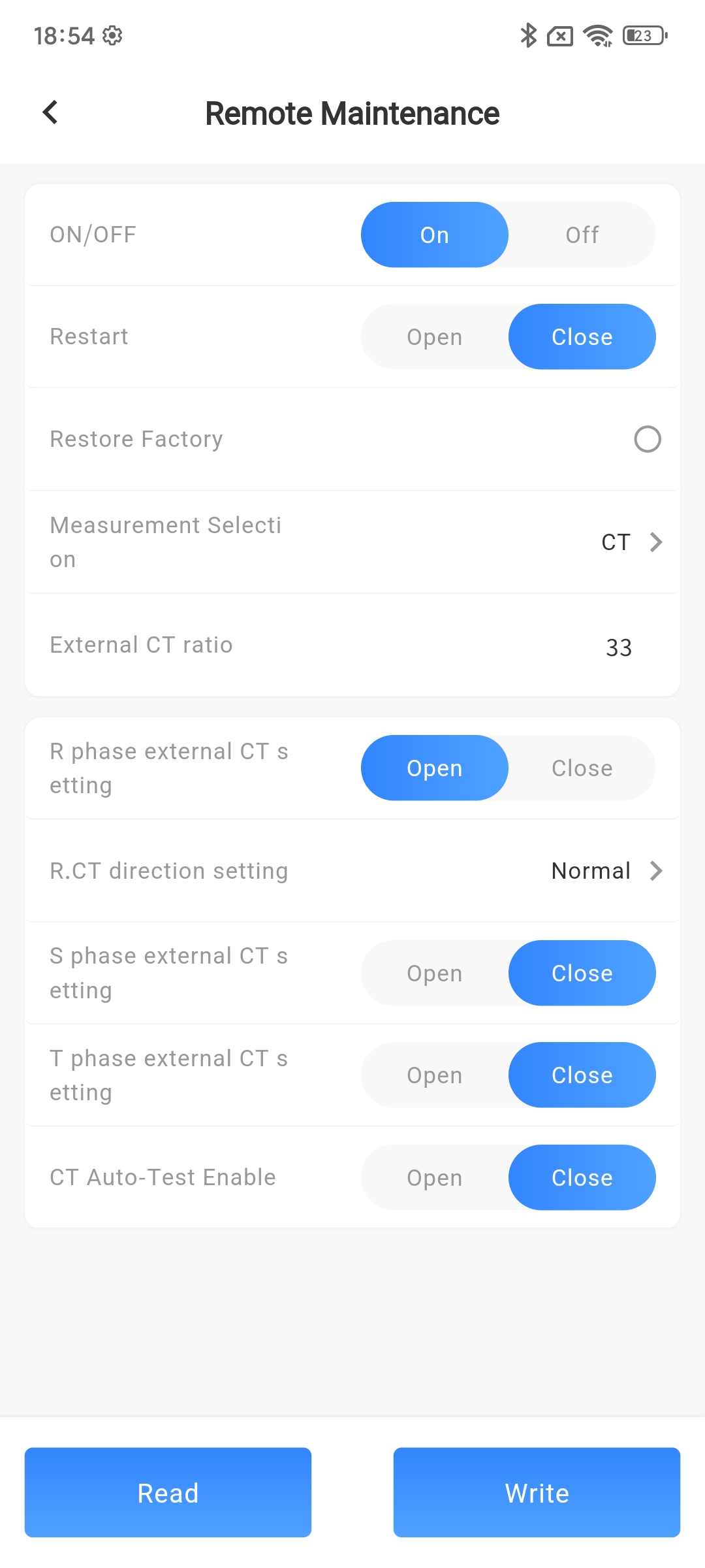
# Remote Maintenance
| Parameter Name | Parameter Description | Parameter Range |
|---|---|---|
| ON/OFF | Default enable, i.e. power on state, disable to enter standby state | Power on/off |
| Restart | After enabling, the machine will restart | Open/Close |
| Measurement Selection | Set according to the actual time in the country/region where the device is located |
Nothing Meter CT |
| CT Auto-Test Enable | After enabling, the CT direction can be set | Open/Close |
| R.CT direction setting | After enabling, perform reverse connection judgment under the condition of battery grid connection. If there is an abnormality, an error message will be given, and the correct CT direction can be manually set | Normal/Reverse |
| S.CT direction setting | After enabling, perform reverse connection judgment under the condition of battery grid connection. If there is an abnormality, an error message will be given, and the correct CT direction can be manually set | Normal/Reverse |
| T.CT direction setting | After enabling, perform reverse connection judgment under the condition of battery grid connection. If there is an abnormality, an error message will be given, and the correct CT direction can be manually set | Normal/Reverse |
| External CT transformation ratio | The transformation ratio is determined by the external CT | |
| R phase external CT enable | After enabling, the CT direction can be set | |
| Electricity meter brand and agreement | The corresponding electric meter brand when connecting an external electric meter | |
| Restore Factory | After enabling, all settings of the machine are restored to factory settings | Open/Close |
# External devices
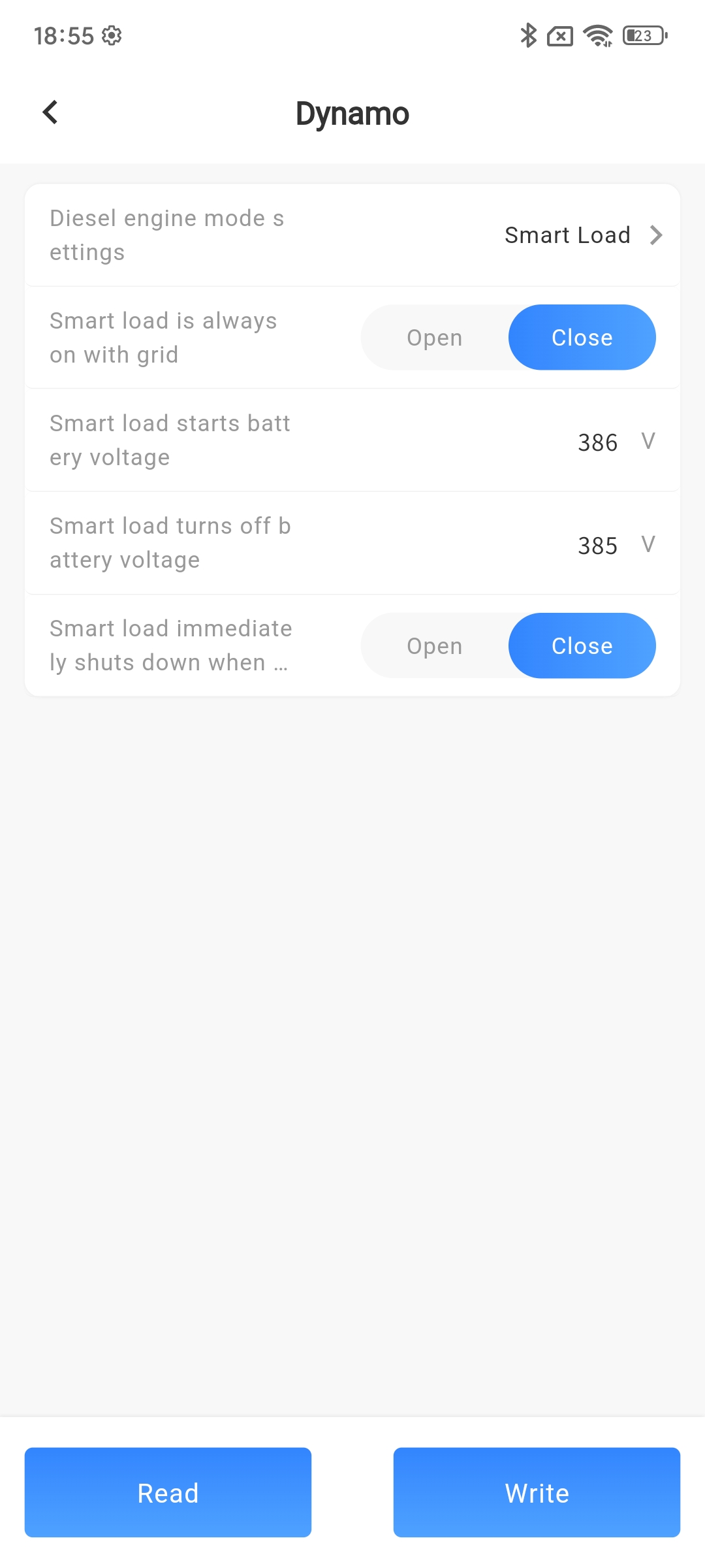
Alternator
| Parameter Name | Parameter Description | Parameter Range |
|---|---|---|
| Diesel engine mode setting | Choose the diesel engine working mode | Power generation output/Intelligent load |
| The smart load of the power grid is always on | After setting, the smart load will be turned on when the power grid exists | Open/Close |
| Intelligent load startup battery SOC (%) | If the battery SOC is greater than this set value, start the intelligent load | Minimum setting 0, minimum unit 1% |
| Intelligent load shutdown battery SOC (%) | If the battery SOC is less than this set value, turn off the smart load | Minimum setting 0, minimum unit 1% |
| When the power grid is disconnected, the smart load will immediately shut down | When there is no power on the grid side, immediately turn off the smart load | Open/Close |
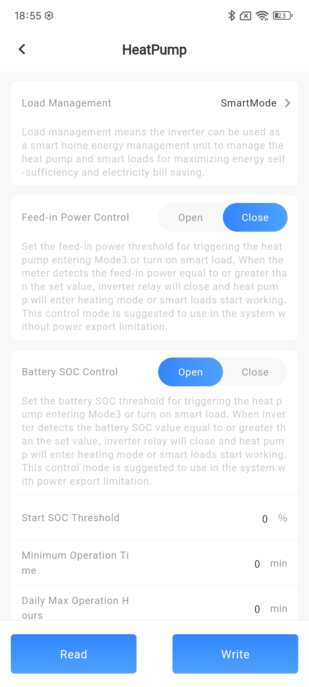
Heat pump
| Parameter Name | Parameter Description | Parameter Range |
|---|---|---|
| Heat pump | Select the working mode of the heat pump | Disable/Manual mode/Smart mode |
| Switch status | If the function mode is selected as manual mode, it can be controlled to turn on or off, otherwise only the current output status can be read | Open/Close |
| Feed-in power control | After enabling, other enabled functions will automatically turn off, and the heat pump will operate according to the set parameters | Open/Close |
| Feed-in power threshold(W) | When the upstream power is greater than the set value, turn on | Minimum setting 0, minimum unit 1W |
| Min operation time(min) | Minimum running time after each opening | Minimum setting 0, minimum unit 1 minute |
| Max operation time(min) | Maximum daily operating time | Minimum setting 0, minimum unit 1 minute |
| Consumption power threshold(W) | When the downlink power is greater than the set value, it will be turned off | Minimum setting 0, minimum unit 1W |
| End SOC threshold(%) | When the SOC of the battery is less than the set value, it will be turned off | Minimum setting 0, minimum unit 1% |
| Batt SOC control | After enabling, other enabled functions will automatically turn off, and the heat pump will operate according to the set parameters | Open/Close |
| Start SOC threshold(%) | If the SOC of the battery is greater than the set value, open it | Minimum setting 0, minimum unit 1W |
| Min operation time(min) | Minimum running time after each opening | Minimum setting 0, minimum unit 1 minute |
| Max operation time(min) | Maximum daily operating time | Minimum setting 0, minimum unit 1 minute |
| Consumption power threshold(W) | When the downlink power is greater than the set value, it will be turned off | Minimum setting 0, minimum unit 1 minute |
| End SOC threshold(%) | When the SOC of the battery is less than the set value, it will be turned off | Minimum setting 0, minimum unit 1% |
| Time control | After enabling, other enabled functions will automatically turn off, and the heat pump will start working according to the set working time period | Open/Close |
| Heat pump operation time | Set the working time period of the heat pump so that the equipment can only work normally during the time period when it can be turned on |
# Quick configuration steps
① Log in to the Smart M app.
② Click on [Device] at the bottom to enter the data list page.
③ Click the [...] - [Configure] button on the right side. (If the device model supports quick configuration, clicking the configuration button will bring up a configuration mode selection pop-up window. If quick configuration is not supported, the page will directly enter the parameter configuration page.)
④ Select Quick Configuration in the pop-up configuration mode selection window.
⑤ In the pop-up quick configuration pop-up page, select the parameter type that needs to be set.
⑥ In the corresponding parameter type input box, enter the parameter value that needs to be modified, and click the [Settings] button.
# Device self check
① Log in to the Smart M app.
② Click on [Device] at the bottom to enter the data list page.
③ Click the [...] - [Configure] button on the right side.
④ In the pop-up parameter configuration page, select the power grid parameter option. (Only machines in some regions support self checking, and the self checking button will only be displayed if the regulations are set to the corresponding region)
⑤ On the power grid parameter page, click the Automatic Detection button.
⑥ Click the Start button on the pop-up page to start the self check.
⑦ Wait for all self-test items on the detection page to complete, and the device will complete its self-test.
# Offline configuration
① Log in to the Smart M app.
② Click on the bottom [Device] to enter the data list page.
③ Find the offline devices under your Plant and click the [...] - [Configuration] button on the right.
③ Select the parameters you need to adjust, modify the content you need to modify, and click the [Create Offline Task] button.
-After clicking the "Create Offline Task" button, the device will create an offline task. When the device connects to the service again, the platform will issue the offline task to the device at a certain frequency.
# Offline task viewing and operation
After completing the offline task creation, you can view the previously created tasks through the [Offline Tasks] button in the upper right corner of the [Parameter Configuration] page and perform operations on related tasks.
Offline task viewing
① Log in to the Smart M app.
② Click on the bottom [Devices] to enter the device list page.
③ Click the [...] - [Configuration] - [Offline Tasks] button on the right to enter the offline task page.
Offline task operation
① Log in to the Smart M app.
② Click on the bottom [Devices] to enter the device list page.
③ Click the [...] - [Configuration] - [Offline Tasks] button on the right to enter the offline task page.
④ Click the [...] button in the bottom right corner of offline task data to perform operations on the current task, and pause unexecuted offline tasks.